Eng-Tips is the largest engineering community on the Internet

Intelligent Work Forums for Engineering Professionals

on/off solenoid activated bypass valve 1

Status
Not open for further replies.

Hien90

Mechanical
Apr 4, 2020
9
0
0
VN
Hi guys,

I am not sure if it is the right place for asking such a question like this. But I am struggling with understanding what the "on/off solenoid activated bypass valve" is. Does anyone know what is the function of this valve and what is the symbol of this valve in the hydraulic schematic diagram?

Thanks and Kind Regards!
 
Replies continue below

Recommended for you

Context, please.

In the absence of any context ... it's a two position single solenoid spring return directional valve which passes fluid in one position and blocks passage in the other position. Which position corresponds to energised or de-energised depends on whether it's normally-closed or normally-open. What it's "bypassing" ... who knows ... hence, the request for some context.
 
I am sorry for not being clear from the beginning. The request that I got is to add an on/off solenoid activated bypass valve to the manifold, which allows flow from P direct back to the tank. I searched for the bypass and it seems like it can be something like a pressure relief valve but I am sure that it is probably something else...

Your file's link is:
 
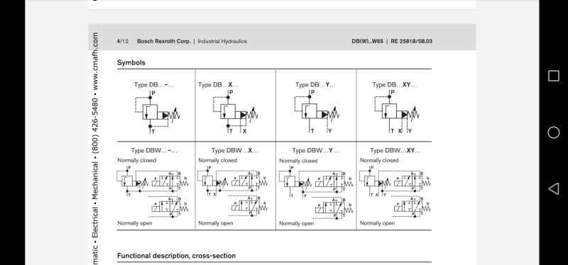
The symbol that you provided, is an adjustable pressure-relief valve. These ordinarily don't have a solenoid.

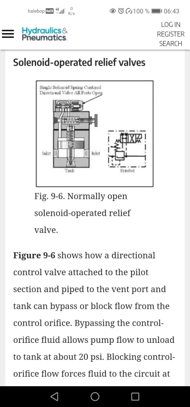
The function that you are describing sounds like a pressure-unloading valve. It can be a plain ordinary two-position single-solenoid spring-return directional valve that allows flow through in one position and blocks it in the other position. It could be either normally-open or normally-closed ... depending on what you want to have happen when the valve power is off. Think about which condition is the "safe" condition. Usually "safe" = "nothing moving" i.e. default condition is vent-to-tank and you have to energise the solenoid if you want pressure. But maybe not.

Watch out for flow capacity. It's going to have a pressure drop across it under full-flow conditions. How much ... depends on the characteristics of the valve that you pick. Where are those characteristics? manufacturer's specifications.

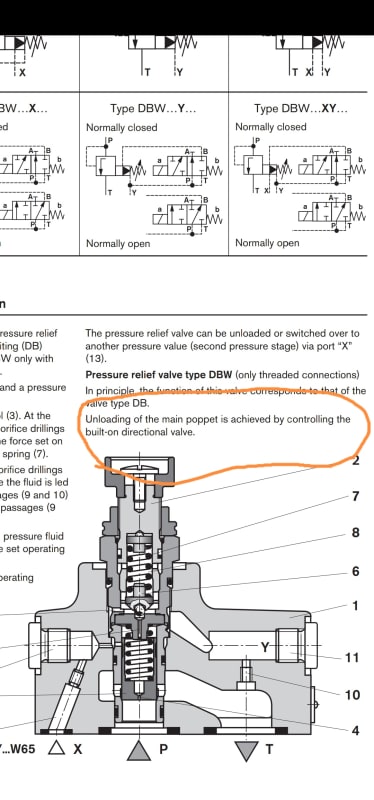
If it's a pilot-operated valve (as opposed to direct-solenoid-actuated), think about where the pilot pressure is going to come from, if you have vented pressure supply to tank.

If the pump is a pressure-compensated variable-displacement pump, think about what happens when it sees low delivery pressure: it goes to max displacement and max flow rate. That is probably not what you want to have happen.

Pressure-unloading valves are used with fixed-displacement gear pumps all the time, to cut down on power consumption and heat build-up under conditions when the rest of the system is not demanding load (both pressure and flow simultaneously).

If the valve is for safety purposes, then this valve may have to be redundant and with fault monitoring. Such valves are available on the market. They require proper integration into the safety system of the machine as a whole.
 
I created a schematic diagram for easier understanding.
Basically what I need is to use the valve for controlling the direction of the fluid flow. I want to keep the motor working even when the cylinder is not working. The reason for that is to not waste a time waiting for the motor to start working.
 
 https://files.engineering.com/getfile.aspx?folder=cd04b839-3ef3-42d9-9b64-336f4b89bb7a&file=Capturea.PNG
Screenshot_20211124_121536_com.google.android.apps.docs_ubn3bb.jpg


Something like this???
 
Yeah, something like this but it looks like a pressure relief valve so I wonder if I can replace the spring with a solenoid in the unloading valve...
 
It's not a matter of "replace spring with solenoid". It's a matter of "use a different valve". The symbol is nothing like that. (The valve internally is nothing like that)
 
The layout you show appears to be a pressure relief downstream the pump back into the tank. The set point is difficult to make out but looks the same as the bypass around the pump?? It really needs to be lower than the pump so that it opens first.

Using a solenoid valve (on/off) in place of the one you show red ringed will drop pressure to virtually zero, so reduce pump loading during "standby".

So opening it will keep the pump running, but at a low pressure. Now how you know when to close that valve I don't know and there could be a lrge shock on the system each time - the pipework will jump at the very least.

Capturea_xtdyc3.png


Remember - More details = better answers
Also: If you get a response it's polite to respond to it.
 
There should be something else, not a relief valve. May I ask how the solenoid valve symbol looks like and how to apply it? I searched on google and there is no one specific symbol for that...
 
Open the link that I gave you in my post from 13:04 today. One of those is the correct symbol for what you are looking for, depending on whether you want normally-open or normally-closed.
 
If I understand well, it can be any type of valve with a solenoid coil?

What I want is exactly what LittleInch said. I need to eliminate the load on the motor when starting and reduce the load when the motor is running but no work is required. The valve will close when the other valves are active. Putting power on the coil should open the valve. So I want to simplify the bypass valve to a single on/off coil that connects P to T. After reading all of the comments above it seems like the closest answer is using an unloading valve, but I might be wrong....

 
Stop suggesting pilot-operated valves - they will not work in this application without a separate pilot-pressure supply!

How much flow-rate are we talking about here? Given that the hoses to the one and only cylinder that is shown are only 1/4", I'm ASSuming that this is a pretty small system.

As far as connecting P to T ... You've got a manifold already. Hopefully it has a spare position available on it. Obtain a direct-solenoid-actuated (NOT pilot-operated!) 2-position spring-return valve from whichever supplier you are already buying the manifold and valves from. Same series of valves as whatever the existing directional valve is. The manifold base has the connections from P and T. The valve will give you ports for A and B. Hose A to tank, plug B. Or vice-versa, depending on whether you want it normally-closed or normally-open. Done. Easy peasy.
 
Status
Not open for further replies.
Back
Top