Continue to Site

Eng-Tips is the largest engineering community on the Internet

Intelligent Work Forums for Engineering Professionals

  • Congratulations KootK on being selected by the Eng-Tips community for having the most helpful posts in the forums last week. Way to Go!

Open Delta-Open Delta Xfmr with GFCI on Secondary Side

Status
Not open for further replies.

milwaukeebob

Electrical
Jun 21, 2004
42
Hello forum members,
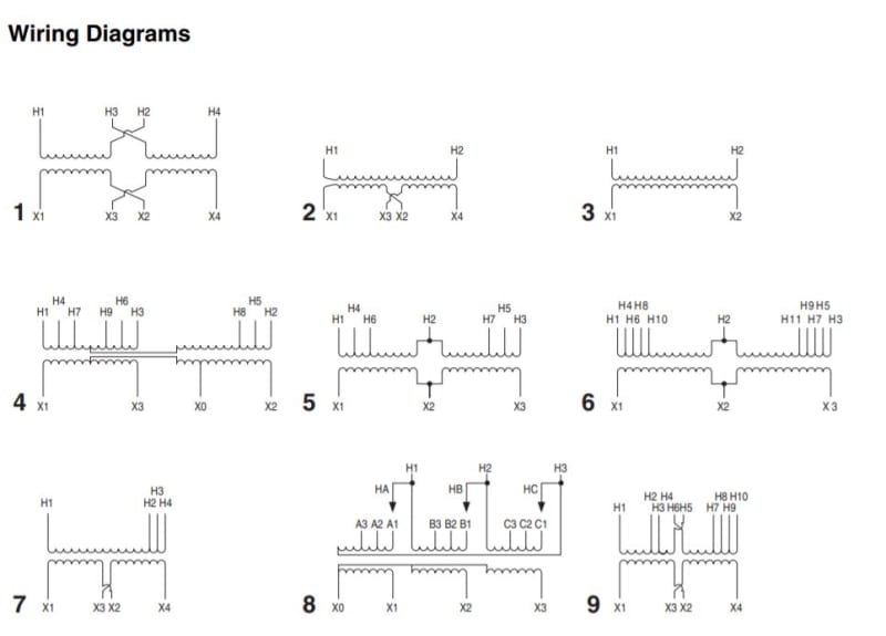
It's been a long time since I posted. Took some time away from the industry but I'm back and looking for some guidance. I just ran into something I've never seen before. Project I'm on has a small 3kVA xfmr 3-phase, open-delta, open-delta winding configuration, 240V primary/120V secondary (see attached pic of nameplate). This xfmr feeds only a single load - an outdoor 120Vac GFCI receptacle. The xfmr is fed from a 3phase, 4wire panel (400V L-L/230V L-N) but with a single-phase molded case circuit breaker...so 230V L-N.

The engineer of record on the job has informed us to connect the primary side 230V single-phase L-N to H1-H2 respectfully with the ground conductor connected to xfmr chassis ground. The other primary taps and winding (H3/H4/H5/H6/H7) are all to be isolated/insulated. On the secondary side the 120Vac L-N to the GFCI is to be connected to X1-X2 respectively (with winding X3 isolated/insulated) and X2 terminated to xfmr chassis ground.

I have only seen open-delta, open-delta once in my career but only on a 3 phase circuit. I've argued this xfmr is not right for the application and violates the Code. Any help is appreciated.

MB


 https://files.engineering.com/getfile.aspx?folder=64d00b56-c522-40a2-942a-7e89c67fdba8&file=Xfmr_pic.jpg
Replies continue below

Recommended for you

This is a strange connection. You are only using one core of the transformer, making it the same as a single-phase transformer. I'm not sure what voltages you would have on the unconnected terminals.
 
Seems WAY overly complicated compared to just using a single phase 240-120V transformer...

I'm wondering if this is someone's idea of trying to have a balanced draw on the 240V 3 phase side from unbalanced 120V loads? But in YOUR CASE, you do not have 240V 3 phase, you have 400V 3 phase, and 3 lines of 240V single phase L-N.


" We are all here on earth to help others; what on earth the others are here for I don't know." -- W. H. Auden
 
Not a code maven but I don't think it violates code.

There are several reasons this is being done up to and likely including Covid. It could be the only xfrmr locally available that will do the job.

Could also be the customer was/is dithering between 120 and a center-tapped 240 requirement so the guy is stacking his odds. Puts in a transformer that will do either, charges the customer for it upfront. If it later changes it's just a wiring change not a transformer change.

Could be it was already in-hand and unneeded for anything else.

Keith Cress
kcress -
 
Thanks jghrist, jraef, and itsmoked. Indeed this is strange and I agree it is way overly complicated versus a standard single phase 240-120Vac xfmr. Those were almost word-for-word my first comments. There's more to the back-story but for the purpose of brevity, I didn't include that. Covid and supply-chain issues did not factor into the decision because these were ordered a long time ago. This was a conscious decision by someone. I want to change it out but unless I have a compelling reason, the project schedule will dictate otherwise.
 
A probable code violation:
and X2 terminated to xfmr chassis ground.
That is acceptable for an equipment ground, BUT:
The secondary of the transformer is a separately derived system and as such requires a system ground.
The installation rules for a system ground are much more stringent than for an equipment ground.
Using an extension of an equipment ground for a system ground would not pass under the codes that I am familiar with.
I'm not sure what voltages you would have on the unconnected terminals.
I'm not sure either.
I don't think that the voltages on the unconnected side may be determined from the information given.
The voltages will depend on the core arrangement.
I suspect that internally that may be two, independent, single phase transformers.
Given that they make a lot of single phase transformers and an open delta, three phase transformer will be a special order, the two transformer solution is probably the cheapest and would avoid possible phantom delta complications.
If the open delta is two independent single phase transformers then the voltages on the unused side will be zero.
If a common core is used, I won't guess at the possible voltages.

Summary: I don't see a violation with the transformer itself, (An AHJ may differ, more out of ignorance than out of knowledge. Never seen that, have we.)
The cost and complexity of supplying a system ground may justify a change.
I would suggest an auto-transformer. *The physical size will be 1/4 and it will not be a separately derived system and the grounding method will be acceptable.
An auto-transformer rated to deliver 1.5 KVA will be adequate.
A lighting transformer may be connected as an auto-transformer and a rating of 0.75 KVA will be adequate.
It may be the same physical transformer as the 1.5 KVA auto-transformer, the only difference being the rating method.


--------------------
Ohm's law
Not just a good idea;
It's the LAW!
 
Bill;
Using an extension of an equipment ground for a system ground would not pass under the codes that I am familiar with.

What would need to be different? Would it be a driven ground rod included in the system ground?

Keith Cress
kcress -
 
Size:
System grounding conductor minimum #6 AWG.
Equipment grounding conductor for a 15 Amp circuit, #14 AWG.
There may also be differences in splicing and connection standards.
Grounding a system by connecting to a bonded/grounded equipment case or enclosure is not acceptable.
I do not have a current code, and there have been relaxations over the years, but I seriously doubt that the code has been amended enough to allow that proposed installation.
Some methods of equipment bonding that are acceptable in some cases such as connecting to a nearby water pipe or connection to a grounded metallic building frame are not acceptable for system grounding.
A system ground for this system could be nearby driven or buried ground electrodes.
At one time system grounding conductors could only be spliced or teed with a compression connector that encircled the conductors. Thermite welding was acceptable.
The code was amended to allow splices and tees to be made with compression "C taps".
I haven't installed a system ground since I don't remember when.
One challenge was a new service in a new occupancy in a shopping center. We had to tap off from a system ground conductor that was very long with no easy way to install a ring type compression connector.
As I remember we used Thermite welding to make our tee connection.
Using a Cad-Weld in a drop ceiling was challenging but possible.
If it had been an equipment grounding conductor we would have used a Servit (split bolt) connector.

--------------------
Ohm's law
Not just a good idea;
It's the LAW!
 
If H2 is connected to a grounded system neutral, I don't see this as separately derived.
The probable code violation I see is using the ground used as a load current carrying conductor. X2 should be connected to neutral, not to the grounded chassis.
I don't think the voltages on H3 and X3 are an issue, since the insulation level should cover whatever potential they rise to. You could bond these to the system neutral also if concerned.
 
H1, H2, H3 is one system.
X1, X2, X3 is the separately derived system.
When installing 480;120/208 Volt lighting transformers in industrial plants, the ground conductor included in the construction of the Teck cable was adequate for equipment grounding but not adequate for grounding the separately derived 120/208 Volt system.
An additional system grounding conductor was installed to ground the 120/208 Volt system.
This is not an auto-transformer so grounding H2 does nothing for the secondary system grounding.
H1, and H2 are connected to L1 and neutral, not to ground. The equipment grounding conductor is connected to the case as it should be.
--------------------
Ohm's law
Not just a good idea;
It's the LAW!
 
I don't think that the voltages on the unconnected side may be determined from the information given.
The voltages will depend on the core arrangement.
Not sure what you mean by the core arrangement, but from the drawing showing the winding of the transformator it would be like this.

H1-H2 = 240VAC > X1-X2 = 120VAC 120/240=0,5
H1-H2 = 230VAC > X1-X2 = 115VAC 230*0,5=115

H4-H2 = 228VAC > X1-X2 = 120VAC 120/228=0,53
H4-H2 = 230VAC > X1-X2 = 121VAC 230*0,53=121

Best Regard A

“Logic will get you from A to Z; imagination will get you everywhere.“
Albert Einstein
 
Can I call you Red? The transformer core; Is it two legged, three legged, two separate legs?
A three phase, three legged core may exhibit a phantom delta effect.
With this transformer, I don't know.
By "core" I mean the iron core, not the number of wires.
--------------------
Ohm's law
Not just a good idea;
It's the LAW!
 
:) With call do you mean call me by phone or just call me Red instead of Redsnake? ;-)
If it is the later you can call me Red or Redsnake or Anna what ever suits you waross or should I say Bill?
If you want to phone I guess I can arrange that too. :)

Well that transformator is a mystery I can't find any data on it, it doesn't seem to exist!
What I did find was this though and number 5 is this one but in this product catalog its a 3-phase 480 V Delta Primary to 240 V.

0_gxbka0.jpg


“Logic will get you from A to Z; imagination will get you everywhere.“
Albert Einstein
 
Hi Anna;
Three phase transformer with a three legged core.
When the primary is fed from a four wire star source, This core arrangement may exhibit the phantom delta effect and back feed voltage into an open primary phase or back feed current into a grounded primary phase.
That is why I suggest that the arrangement (the number of legs on the transformer iron core) may have an influence on the voltage of an unconnected phase.
The unused leads are to be insulated in any event so this is a moot question.
three_legged_core_zitxfm.jpg


--------------------
Ohm's law
Not just a good idea;
It's the LAW!
 
I prefer to call you "Red" or "Anna".
In your diagram, #4 is interesting.
It looks like a "Tee" connection.
That was common as an industrial lighting transformer back in the late 60's and early 70's.
480 Volts to 120/208 Volts, generally 25 KVA or 37.5 KVA.
It is an adaptation of the Scott connection.
The Scott connection was originally developed to convert three phase to two phase and two phase to three phase.
The Scott connection may also be used to transformer three phase to three phase.
The principle difference between a "Tee" connection and a "Scott" connection?
The "Tee" connection has a buried connection between the left hand windings and the end of the right hand windings.
In the "Scott" connection both the center tap on the left hand winding and the end of the right hand winding are brought out and may or may not be connected, depending on the arrangement of the two phase system.
And;
The tee connection does not have an H0 tap.
For the majority of two phase systems they are not connected on the two phase side but are connected on the three phase side.
So;
A Scott transformer may be used for three phase to three phase transformation, but the "Tee"transformer is not suitable for two phase use.
Whenever I encounter someone calling a center tapped transformer a two phase system I always think:
"Another person who is not old enough to have studied a true two phase system."
As far as I know both the Scott arrangement and the tee arrangement used two single phase transformers with special taps.
I have never been able to find an evaluation of the advantages and disadvantages of the tee arrangement.
Can anyone help me with that?

--------------------
Ohm's law
Not just a good idea;
It's the LAW!
 
Thanks Keith. I've been looking for something like that for years.
They are calling both versions a Scott-Tee transformer.
I learned 2ph/3ph version as the "Scott" transformer and the 3ph/3ph version as the "Tee" transformer.
The tap positions and interconnections are not easily interchangeable between the two versions.
Figure 4 is a 3ph/3ph application.
The right hand winding of the 3ph/3ph is a lower voltage than the left hand winding. About 87%.
If a 2ph/3ph version is used for a 3ph/3ph application the winding portion past the 87% tap is often unused.
The plants where I used to see the tee transformers typically ran the motors on 480 Volts, the high-bay lighting on 480/277 Volts and the tee transformers were used to supply 120/208 Volts for office lighting, receptacles and appliances.
Slight regulation differences between phases were unimportant.
The Scott principle is very vesatile.
It may be connected for 3 Wire 3ph, 4 wire 3ph. 3 wire 2ph, 4 wire 2ph or 5 wire 2ph.
Different applications may require different taps and transformer voltage ratings.
eg: An 87% tap or an 87% voltage rating.
Also, H0 and/or X0 may or may not be present on either the primary or secondary windings depending on the application.


--------------------
Ohm's law
Not just a good idea;
It's the LAW!
 
Waross said:
This is not an auto-transformer so grounding H2 does nothing for the secondary system grounding.
H1, and H2 are connected to L1 and neutral, not to ground.
Except the neutral (also known as the grounded conductor), is grounded at the service. It may not be an auto-transformer as delivered, but it is wired as such the way I suggested above.

ECM said:
A separately derived system is a premises wiring system with no direct electrical connection to conductors originating from another system [Art. 100 definition and 250.20(D)].

I suggested directly connecting H2 and X2 to the system neutral, so nothing here is separately derived if wired as I suggest.

Chassis should be grounded, but no transformer terminals should be, since this would create a second neutral-ground bond.


Hi Stevenal;
Your suggestion is probably a better solution than the present design.
Pros:
1. Using the neutral rather than the Equipment Grounding Conductor (EGC) is safer. An open neutral is immediately apparent and must be repair before the circuit may be used. An open EGC may go unnoticed until there is an incident related to ungrounded equipment. (Hence the stricter rules for System Grounding Conductors.
2. Despite the code, with 7.2 Amps on the primary and 14.4 Amps on the secondary, a #6 AWG System Grounding Conductor may be a bit of overkill.
3. I have met more than one older, seasoned and technically aware AHJs that would probably accept your solution.
Con:
1. Not all AHJs would accept your characterization as an auto-tranformer. Beware of younger AHJs who are going by their interpretation of the code and have not yet developed the common sense judgment that comes from more years in the field.
2. The OP is looking for reasons to justify replacing this transformer.

I respect your suggestion, Stevenal.

--------------------
Ohm's law
Not just a good idea;
It's the LAW!
 
Status
Not open for further replies.

Part and Inventory Search

Sponsor