r-struct
Structural
- May 12, 2018
- 19
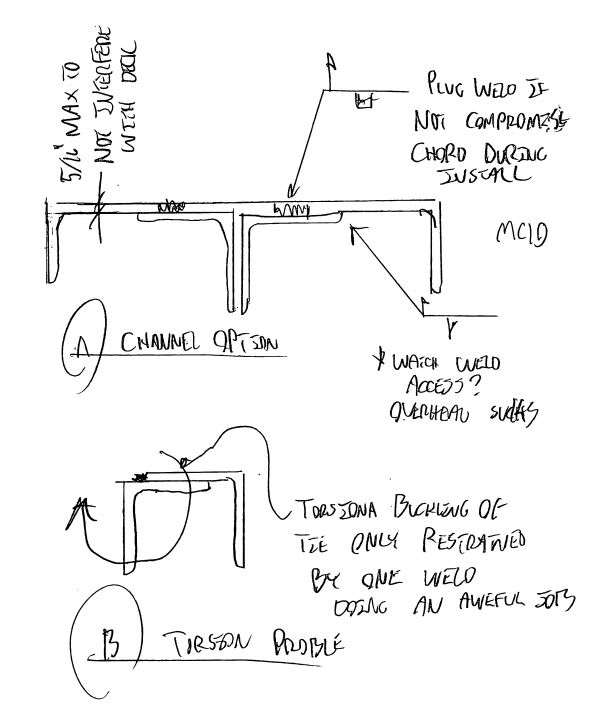
When the top chords of open web steel joists (OWSJ) are used as boundary elements (struts/chords) of a diaphragm, one detail we are looking to use to transfer axial forces between OWSJs is that of tie angles as shown below.

This is consistent with the suggested detail from some joists manufacturer to have a more direct load path for the axial load from one OWSJ chord to the next OWSJ chord, rather than passing the axial load through the joist seat. One other option is to have a tie plate on top of the OWSJ top chords but this option would cause some slight interference to the steel deck above.
A few concerns/questions I have with the use of tie angles, for anyone who have used these in the past or who have looked at this in detail previously:
1. How is the minimum length of the angle at each OWSJ side established?
2. When checking the capacity of the tie angles, can its unsupported length be assumed to be close to zero or should it be close to 1200mm based on the sketch? The tie angles would almost be continuously supported by the OWSJ top chord which is also practically continuously supported by the steel deck diaphragm.
3. With the angles loaded only through the intermittent welds shown, I am a bit concerned with the eccentricity of how the axial load is delivered to and from the angles.
4. Should it be a concern that the angles will be held in place only by the same welds that are used to transfer the axial load?
Any further insights and comments with this detail is appreciated. Thanks in advance.


