Hi,
I'm undertaking a design check for a large 12m diameter cover slab. The slab has a number of large openings(2.9 x 2m the largest).
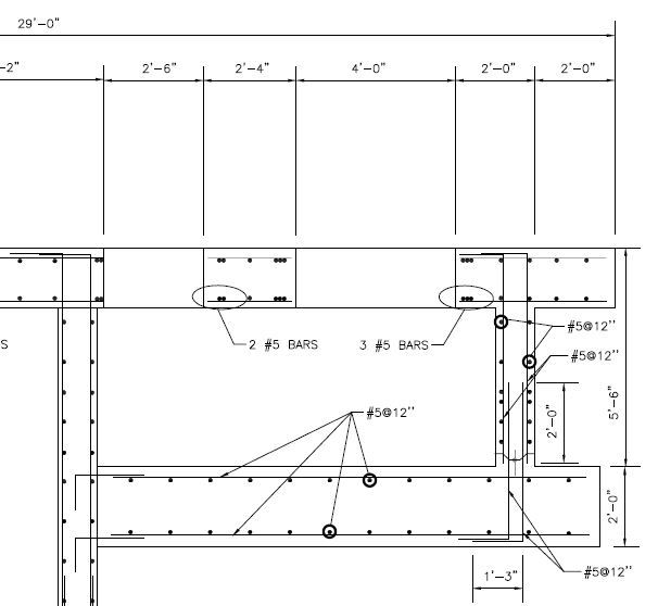
What I'm not sure about is how to determine the reinforcement at the corners of these openings, I see the practice is to provide diagonal bars but I'm not sure how to analyse this.
If anyone could point me in the direction of a thread or reference it would be much appreciated.
Thanks and regards,
Edu
I'm undertaking a design check for a large 12m diameter cover slab. The slab has a number of large openings(2.9 x 2m the largest).
What I'm not sure about is how to determine the reinforcement at the corners of these openings, I see the practice is to provide diagonal bars but I'm not sure how to analyse this.
If anyone could point me in the direction of a thread or reference it would be much appreciated.
Thanks and regards,
Edu
") Okay, and to control cracking you place bars diagonally at the corner? Then I can pick a section and check it for cracking?
Okay, and to control cracking you place bars diagonally at the corner? Then I can pick a section and check it for cracking?