Continue to Site

Eng-Tips is the largest engineering community on the Internet

Intelligent Work Forums for Engineering Professionals

  • Congratulations KootK on being selected by the Eng-Tips community for having the most helpful posts in the forums last week. Way to Go!

Operating Pumps in paralle even thoough they are not originally designed for that purpose 2

Status
Not open for further replies.

Bultum

Civil/Environmental
Oct 8, 2019
11
HI,

I am currently working on rectifying anissues at a pump station. In short I have three pumps connected to one suction line and one discharge line. The pumps are designed to operate individually, one duty and 2 stand by. The pumps work perfectly fine as long as there is a positive pressure going in. However once the water in the storage drops below the pump intake line, there is negative pressure in the suction. The issue is during this time, we have excessive air leaking through the off-duty pumps (packing gland). I have considered mechanical seals, but they are very expensive - especially for an old pump and I'm not sure how effective they are.

Since the pumps have VSD installed on them, I was thinking running the three pumps in parallel. So reduce the speed of the pumps. I know I will be operating the pumps inefficiently but if I can prevent air getting into the system, I can prevent the pumps from failing.

what are your thoughts?

By the way, i'm a grad engineer. Been in this job for only three months so i'm new to this stuff.

Thank you
 
Replies continue below

Recommended for you

Isolate the off duty pumps?

Running in parallel like that might work but a lot depends on the pump curves and system curve. I think it's not likely to work well.

Maybe look at the seal design to see if you can get different ones

Remember - More details = better answers
Also: If you get a response it's polite to respond to it.
 
Look at a non return valve on the inlet of each pump, this will overcome leakage from the idle pump.

It is a capital mistake to theorise before one has data. Insensibly one begins to twist facts to suit theories, instead of theories to suit facts. (Sherlock Holmes - A Scandal in Bohemia.)
 
@littleinch, yes running like that might not work well. But they operate under this condition maybe two or max three times a year. Other times, The water level is always higher than the pump so as long as there is positive pressure going in, they work perfectly fine.

My main aim is to prevent the pumps from failing at that critical point when the pressure transition from positive to negative.

@artisi we do have A NRV at each pump outlet, but installing it on the inlet would be challenging as there is not enough space in the Pump station room

Has anyone ever come across a situation where the pumps have been repurposed or mode of operation has changed. My understanding is the NPSHA and NPSHR are not effected.
 
Yes, but it all depends on the pump curves and system curve.

I assume when you operate two together you are looking for more flow and something is letting you do that on the discharge side (valve more open or something?)

Parallel operation is best at a steep part of the pump curve.

More data required.

Remember - More details = better answers
Also: If you get a response it's polite to respond to it.
 
As pointed out by LI, 2 pumps in parallel is basic pumping, nothing special, but a lot more data is required for a sensible answer.
And while ever you are entraining air from the 3rd pump you are just spinning wheels.

Give us the static head of the system, the total head with 1 pump on operation, the pump curve and we might be able to make some sense of your thinking.

It is a capital mistake to theorise before one has data. Insensibly one begins to twist facts to suit theories, instead of theories to suit facts. (Sherlock Holmes - A Scandal in Bohemia.)
 
Do you have a provision on the packing gland where you can supply pressurized water to the standby pumps in that situation? A line from the discharge, or just city water (make sure there is a check valve so you don't get backflow.)
 
I have the pump curves, but the system curves are old. i'm not sure how to make one. These pumps maintain pressure in town. We have numerous valves, PRVs along the way and i'm not sure how to incorporate those onto my system curve. Graduate engineer problem
@LittleInch i am not sure what you mean by "something is letting you do that on the discharge side (valve more open or something?)"?

@1gibson i have thought about supplying pressurised water from the inlet to the suction line. Perhaps a DN100 pipe. My question is how does that effect the pump. Wouldn't water just circulate around the pump. As you increase the pressure output of the pump, lest say to 40m, you would have 40m going into the suction line. would that reduce the pressure in town? i'm not sure what you mean by "provision on packing gland", you mean somehow connect the pressurised town water to the pumps through packing gland? is that possible?
 
 https://files.engineering.com/getfile.aspx?folder=15b6cbe3-6e3e-474a-9541-bdacc8c02b1b&file=Pump_Data_Sheet.pdf
You say this happens when the water level drops below the pump intake nozzle at the tank, so even if you resolve the reverse leakage of air through the standby pumps, you will still have air being entrained into the intake nozzle at the tank. Find ways to prevent the level dropping so low. Tell us why level drops at the tank if you need help with this.
 
@georgeverghese, i haven't thought about the air getting in through intake nozel at the tank. is that possible, given that the tank is 4m deep below the pump intake nozel. The suction line is connected to the bottom of the tank. The tank gets its water from a WTP. If for any reason there is a failure at the WTP, the water in the tank drains as its pumped to town. Hence, we have a short window to repair the WTP and get it back online.

There has been a case where the WTP failed and it took longer than expected to get it back online. And then the pumps failed at that critical level. At which point the pressure in town dropped for few hours. If we do have access to the full tank, we can double the time we have to fix the WTP.

So that's the issue, we can prevent the level in the tank from dropping all year, but the one day it fails, especially if its during summer months, the town will loose water.
 
By the way Thank you to everyone who has shown interest in my query. Thank you LittleInch, Artisi, goergeverghese, 1gibson.
 
Your initial question has been answered, whether to your satisfaction we have no idea.
Stop the air leakage from the standby pump gland and that problem goes away, if you require more input on the hydraulics of the pumps and system - - you need to give a lot more detail.


It is a capital mistake to theorise before one has data. Insensibly one begins to twist facts to suit theories, instead of theories to suit facts. (Sherlock Holmes - A Scandal in Bohemia.)
 
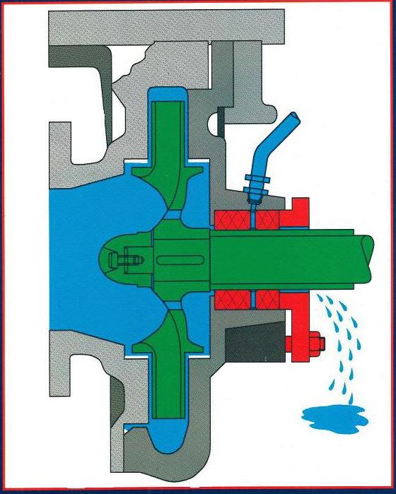
If the pump is designed with packing, it will normally have a connection in the packing case that can be used to inject liquid into the center of the packing stack. There would be a spacer ring called a lantern ring installed to line up with this port. The pressurized water would be connected to the lantern ring connection and a very small amount of it would leak inward to the process. Do an internet search for Lantern Ring and Packing Flush or Gland Water.

Capture_y3atnu.jpg


Johnny Pellin
 
Do you have any details ( drawings, pictures etc) of the packing gland and gland material.

It might be if you have anything that is chevron like that all you need to do is reverse one of the layers to prevent inflow rather than the outflow scenario most of the packing is designed to withstand, but the devil is the details....

also have you tried just removing the ancient packing and replacing it with some newer more resilient packing material?

trying to do something about the seal may be far easier than any other action.

Remember - More details = better answers
Also: If you get a response it's polite to respond to it.
 
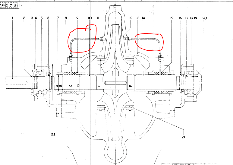
The lantern ring flush @JJPellin suggests would typically solve the problem of reverse air flow into the suction manifold. To prevent the pumps from dry running with no water from the intake nozzle at the tank, you should install a low level trip to stop the pumps and avoid mechanical damage.
 
Lantern_ring_wkhnpb.png


material_list_tecuxy.png


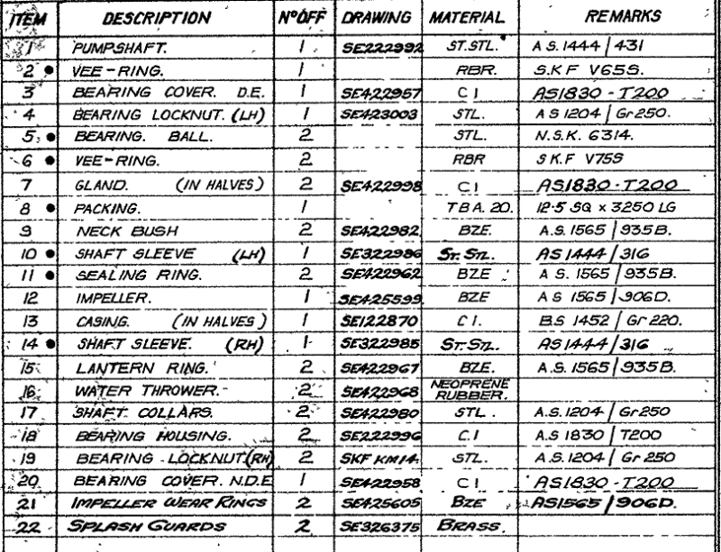
Thank you to everyone who has given me ideas. I have located the lantern ring, i will work on renewing the packing glad and investigate how supply pressurised water to the packing gland.
 
One last question looking at the comment @georgeverghese made, i believe he is talking about formation of Vortex. is there like an anti-vortex device that can installed on the inlet pipe? i have looked online, but besides a lot of theory, i couldn't find any product on the market.
 
Fmoh.
Where did the vortex come from and why are you raising the question, vortex flow entering the pump inlet hasn't been mentioned and isn't part of your problem.

Water to the gland of the stand-by pump can supplied directly from the discharge side of the system - 3/8" pipe should be sufficient on a correctly packed gland.

Suggest you address one point at a time as there are still many unanswered question to be addressed on this operation to which we currently have no information.


It is a capital mistake to theorise before one has data. Insensibly one begins to twist facts to suit theories, instead of theories to suit facts. (Sherlock Holmes - A Scandal in Bohemia.)
 
To answer this recent query re the vortex breaker, can we first see a sketch of the intake nozzle arrangement at the tank and the line going to the pumps? Yes, in most cases, installing a vortex breaker on the pump suction intake nozzle will help to lower the low level trip setting, but you still have to trip out the pumps at some point. Good that you found the lantern ring assembly and the gland flush connection for this pump set.
 
Status
Not open for further replies.

Part and Inventory Search

Sponsor