Eng-Tips is the largest engineering community on the Internet

Intelligent Work Forums for Engineering Professionals

Optimize design with Catia FEM tool

Status
Not open for further replies.

reutov_tv

Industrial
Jan 16, 2024
33
0
0
US
Hello.

I'm asking for help.
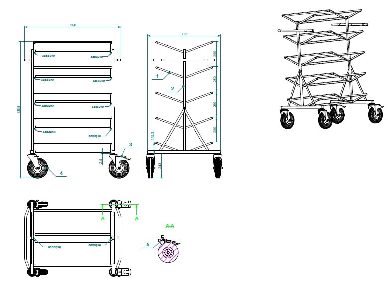
Is there any way to optimize this design? The welding should be kept.
This is the cart on which the shelves are placed.
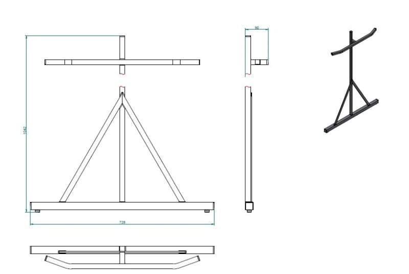
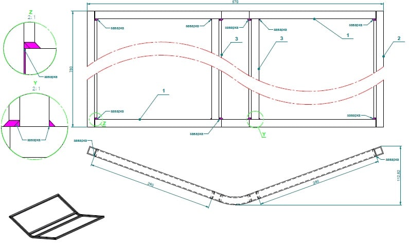
I have only one idea so far - remove one Bar on the "support_hor" component and move the second Bar to the center.
And perhaps to reduce the thickness of the structure profile wall. Now it's a square thin-walled profile.

I've got a default Catia v5 FEM module for structural analysis. But if I understood correctly help documentation, it can only solve linear problems, and for assemblies you need a nonlinear solver.
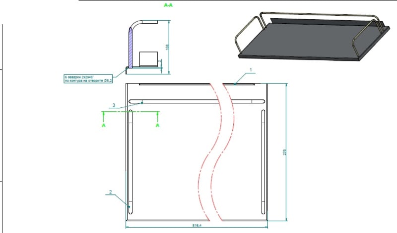
If I am wrong, please help me to make a calculation diagram for this cart. I think everything is clear here with the load - distributed vertical load on the part "Support_hor".
I don't know what boundary conditions should be set.
Maybe just fix the two lower horizontal bars?
Load on the shelves - I don't know yet, but let's assume 30-50kg.
The material of the frame is just galvanized steel.
My skill level in FEM - beginner, a couple of times made analysis for a simple sheet bracket in Catia v5.

Regards,
reutov-tv
 
 https://files.engineering.com/getfile.aspx?folder=d82b8de3-0d46-4afd-af1c-5ba9e3d6f530&file=ASSY.jpg
Replies continue below

Recommended for you

ASSY_yyazpq.jpg

Shelf_vphmow.jpg

Support_vert_gqoxpm.jpg

Support_hor_mcsrtf.jpg
 
what are you trying to optimise for ? weight ? cost??

what are the constraints ? Do you Need 5 shelves ? Do they all have to have the same load carrying capacity ??

"Hoffen wir mal, dass alles gut geht !"
General Paulus, Nov 1942, outside Stalingrad after the launch of Operation Uranus.
 
agree - optimize for what? why?

"for assemblies you need a nonlinear solver" - nope, this is nonsense.

You are going to need accurate material properties. And some strength data for the welded joints.

 
Good evening.

I would like to join the practical study of FEA with this work task.

As a designer, I see optimization in weight reduction or in improving the design in terms of manufacturability. All of this generally results in a lower price.

Constraints: distributed force loaded each shelf with a total weight of 200kg so one shelf loading force is 20kg.

I would also like to ask.

1. What is the most suitable way to specify fasteners in the assembly?
-standard part as solid element (PartBody in Catia terms) obtained from standard catalog.
-Virtual bolt or Virtual connection.
-by imposing constraints on movement in the Assembly design module (for example, to combine axes of holes of two parts, or to make contact of faces).
-something else.

2. What physical properties should be set for the components of this assembly? In my opinion, the components of the assembly represent a frame. But in Catia only the following types are available:
-bar
-beam
-shear panel
-shell
-solid

3. In which cases should the Isostatic Restraint function in FEM Catia be used? This seems to be a statically defined restraint system.

4. Is it possible to estimate the maximum load for such assembly and see the weakest points(with adequate error) in case of beginner using CATIA FEM like me?

5. Welding. What is the best way to set it in such an assembly? Why do they say about welding that it is a big hassle for FEM analysis?

Thank you for your answers.
 
SWComposites said:
"for assemblies you need a nonlinear solver" - nope, this is nonsense.

It is from Catia Generative Structural Analysis User's Guide.
For static case solutions, one can say that:
l If there is no contact feature (either virtual or real), no pressure fitting property and no
bolt tightening (either virtual or real) feature, then the problem is linear, that is to say,
the displacement is a linear function of the load.
l If there is at least one contact feature (being virtual or not) or pressure fitting property or
bolt tightening (being virtual or not) feature, then the problem is non linear, that is to
say, the displacement is a non linear function of the load.


what is stated in CATIA doc is correct, BUT, you don't need to include contact or bolt tightening or similar in a FEM to have a useful assembly model. And for beginners, I very very strongly recommend not using any contact or other non-linear features until you master the basics of linear static FE analysis.

The most suitable way to specify fasteners for a FEM is to NOT include them; just contact the parts together in the model, extract local forces, and calculate fastener loads by hand outside the FEM.

Your structure probably can be quite well modelled only using beam elements.

Not familiar with the Iso Restraint function. Strongly recommend setting up your own constraints so you learn how those work, and not just using some black box thingy.

To estimate "weakest points" you need to understand strength of materials and failure modes. And don't forget to check buckling failure modes of the structure, not just static strength.

Welding - ugh - the material properties are different in the area of the weld, both in the base material and in the weld material; the weld material geometry is complex and has to be idealized; and many more complications; you will need weld strength test data for your assembly components.
 
Hello.

Could you clarify these points:

SWComposites said:
any contact or other non-linear features
- what other features refer to non-linear?

just contact the parts together in the model, extract local forces, and calculate fastener loads by hand outside the FEM.
- Do you mean fastened parts should be constrained by Contact in Assembly context that is they should be restricted from mutual penetration and movement relative to each other?
Then I'm not quite sure what you meant by the term non-linear ContactFeature.

To be honest, I don't remember much from the course on "Strength of materials". It is unlikely that I will be able to calculate fasteners analytically and quickly.But I was able to do that calculations in my student years.

To estimate "weakest points" you need to understand strength of materials and failure modes. And don't forget to check buckling failure modes of the structure
Could you give little more details about "failure modes"?
And how difficult is buckling checking with FEA?

I always considered that weakest points of a structure are points with the maximum stress, which in turn linearly depends on the deformation (in static linear case).
 
the weld material geometry is complex and has to be idealized; and many more complications;

Is it possible to simplify welding scheme, for example, by replacing welding with something else?
I understand that the simpler the model, the lower the accuracy, but at the moment I would like to learn how to make only estimated (approximate) calculations at the level of designer (not a stress engineer).
 
reutov_tv said:
I don't remember much from the course on "Strength of materials". It is unlikely that I will be able to calculate fasteners analytically and quickly...

Could you give little more details about "failure modes"?

Forget using FEM on this thing for right now. Go back and brush up on statics, strength of materials, various failure modes etc. so that you can analyze this thing by hand first. It's relatively straightforward (it's just a bunch of beams/columns). To perform an FEM analysis that is of any use, you need to do at least some basic hand calcs anyways (to make sure your model is at least somewhat connected to reality), so you'll need those hand calc skills either way.
 
Status
Not open for further replies.
Back
Top