-
5
- #1
milkshakelake
Structural
What do y'all do to optimize workflow? I'll list my own stuff with my specific setup and software. (Requested by bookowski, but I'm also interested.)
General
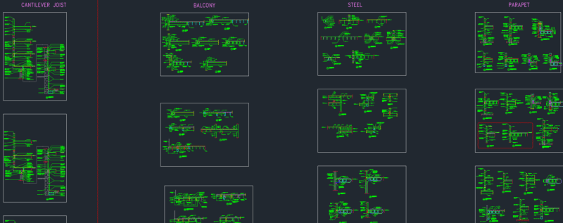
-Have several sheets of standard details that applies to almost any situation. For example, steel details that cover bracing, moment connections, base plates, etc. Aggresively reduce any details you need to draw specifically for any project.
-Any time a new detail is created, put it into a gigantic AutoCAD file of standards. I separate it by material, like having one for cold formed steel. The file itself should be organized into lots of different situations, like CFS on existing building, CFS with conc deck, CFS with plywood/Dragonboard, etc. Run quality control on this file once in a while for organization and weeding out outdated details.
-Put things into schedules as much as possible in order to not draw specific details.
-There are lots of things I use Excel for because it's specifically tailored to my typical projects and materials. Minimize the number of inputs. Software is more versatile, but usually it's faster to use a focused, purpose-built tool. Also, document every assumption made and possible "quirks," like something not working below or beyond a certain load because the assumptions will be broken. Make error messages for those quirks whenever possible using conditional formatting, IF statements, or VBA.
-Avoid VBA in spreadsheets unless it's strictly necessary. People can't understand it.
-Fully done, perfect examples of each type of building (CFS, wood, steel, etc) available to drafters as a starting point.
-This is gonna sound Machiavellian. But if you have employees, reduce thinking as much as possible through standardization. It speeds things up and reduces errors, and helps build upon gained knowledge. Almost nothing should be reinventing the wheel.
ETABS
Start every project from a standard ETABS file with:
Steel
-Export beam and column sizes from ETABS as a drawing, and paste into AutoCAD as a separate layer.
-For ETABS, I haven't found a way to easily export shear reactions, but I made a video for drafters on how to get it.
-ETABS will generate elevations with bracing. I delete column sizes so it doesn't get confused with the column schedule.
-Put concrete piers, base plates, anchor bolts, and column sizes all into one column schedule. No need to make separate details for each base plate; have a few typical situations.
-Have base plate standards for maximum axial load of each column size, and another one for a certain amount of moment together with anchor bolt sizes for your typical pier/footing size.
-Room for improvement: I'm experimenting with ETABS column schedule creation.
Foundations
-Have schedules DRAFTED for most cases of isolated and strip footings with different sizes and bearing pressures. I have eccentric with wall, eccentric without wall, different pier and base plate sizes, etc. This takes absurdly long to design, so I automated it with VBA scripts. I have about 100 of these schedules. Drafting them took a few days. This is a huge advantage because the footing can be selected by a drafter when they have the ASD load.
-For standards, I have interchangeable bottom and top details that are separated by a break line. So if you want mat footing supported wall with CFS joists, you can do that. Same thing with steel beams, just change the top part.
-I have a spreadsheet for grade beams. Just enter footing dimensions and loading, and it designs it. This is possible in software, but a focused spreadsheet does it faster with fewer clicks.
-I have a spreadsheet for bearing wall axial loading. It has buttons for different stud spacings (12" for wall, 16" for studs) and fills in most values automatically from a few basic questions, like what is the wall/floor material and usage. Only numbers you need to input is the number of stories, story height, and span.
-Room for improvement: A tool to take foundation loading from ETABS and spit out footing schedules. That part is currently done manually.
CMU
-All long bearing walls will have #5@24", which works for 100% of my building sizes. Shear walls will have rebar in each cell and unfortunately needs to be calculated.
-Steel bearing plate on CMU has a simple to use schedule for max load for W8, W10, W12, etc. up to about 50 kips. Uneconomical, maybe, but it saves design time.
-Room for improvement: A spreadsheet to take forces from ETABS and automatically design shear walls (I don't trust the built-in ETABS design tool too much).
Cold formed steel
-I use CFS software. I've made pretty much every joist and beam size in a standard folder, since it takes time to build them. They get copied when needed.
-I have a spreadsheet for stair beams. You input the dead and live load, span, and stair opening size, and it calculates all the uniform and concentrated loading on the stairs. This gets input into CFS. There's probably room for improvement if I learned the CFS API and linked the program to the spreadsheet, but that would also introduce usability issues with engineers in the office.
-Standard stud schedules for number of stories, joist span, and flooring material. About 30 of them.
-Room for improvement: A spreadsheet where you put beam/joist loading and it automatically picks a section size. CFS can't do this natively.
Wood
-I suck at wood.
Concrete
-Standard procedure made for obtaining results from SAFE using 1' on center design strips, which eliminates thinking.
-Excel file for column size determination using axial only. In my size of buildings, moment+axial never really controls. I'll still do an automatic P-M calculator in the future.
-Forget about direct design method. We never get nice rectangular bays.
-I made a guide on long-term deflection with load cases explained.
-I made guides on transferring between ETABS and SAFE, transfer slabs, soil subgrade calculation for mats, etc.
-Make a drafter lay out the rebar based on rules of thumb. Have an engineer design it.
-Room for improvement: Importing ETABS data for column and shear wall design, exporting schedules into AutoCAD.
General
-Have several sheets of standard details that applies to almost any situation. For example, steel details that cover bracing, moment connections, base plates, etc. Aggresively reduce any details you need to draw specifically for any project.
-Any time a new detail is created, put it into a gigantic AutoCAD file of standards. I separate it by material, like having one for cold formed steel. The file itself should be organized into lots of different situations, like CFS on existing building, CFS with conc deck, CFS with plywood/Dragonboard, etc. Run quality control on this file once in a while for organization and weeding out outdated details.
-Put things into schedules as much as possible in order to not draw specific details.
-There are lots of things I use Excel for because it's specifically tailored to my typical projects and materials. Minimize the number of inputs. Software is more versatile, but usually it's faster to use a focused, purpose-built tool. Also, document every assumption made and possible "quirks," like something not working below or beyond a certain load because the assumptions will be broken. Make error messages for those quirks whenever possible using conditional formatting, IF statements, or VBA.
-Avoid VBA in spreadsheets unless it's strictly necessary. People can't understand it.
-Fully done, perfect examples of each type of building (CFS, wood, steel, etc) available to drafters as a starting point.
-This is gonna sound Machiavellian. But if you have employees, reduce thinking as much as possible through standardization. It speeds things up and reduces errors, and helps build upon gained knowledge. Almost nothing should be reinventing the wheel.
ETABS
Start every project from a standard ETABS file with:
-Typical sizes of members, slabs, walls, etc.
-Auto select lists for beams and columns (like W10, W10 col, etc.)
-Load combinations
-"Once in a while" combinations like seismic overstrength combinations (it doesn't slow the analysis)
-Nonlinear load cases switched off (switch on when needed; this will destroy analysis speed by 10 to 100 times when turned on)
-Separate file for Auto Construction Sequence turned on (slows the analysis; only use when needed)
-Load combinations for wind (ASCE 7-10+ lower wind speed) and seismic drift (no limit on Cu)
Steel
-Export beam and column sizes from ETABS as a drawing, and paste into AutoCAD as a separate layer.
-For ETABS, I haven't found a way to easily export shear reactions, but I made a video for drafters on how to get it.
-ETABS will generate elevations with bracing. I delete column sizes so it doesn't get confused with the column schedule.
-Put concrete piers, base plates, anchor bolts, and column sizes all into one column schedule. No need to make separate details for each base plate; have a few typical situations.
-Have base plate standards for maximum axial load of each column size, and another one for a certain amount of moment together with anchor bolt sizes for your typical pier/footing size.
-Room for improvement: I'm experimenting with ETABS column schedule creation.
Foundations
-Have schedules DRAFTED for most cases of isolated and strip footings with different sizes and bearing pressures. I have eccentric with wall, eccentric without wall, different pier and base plate sizes, etc. This takes absurdly long to design, so I automated it with VBA scripts. I have about 100 of these schedules. Drafting them took a few days. This is a huge advantage because the footing can be selected by a drafter when they have the ASD load.
-For standards, I have interchangeable bottom and top details that are separated by a break line. So if you want mat footing supported wall with CFS joists, you can do that. Same thing with steel beams, just change the top part.
-I have a spreadsheet for grade beams. Just enter footing dimensions and loading, and it designs it. This is possible in software, but a focused spreadsheet does it faster with fewer clicks.
-I have a spreadsheet for bearing wall axial loading. It has buttons for different stud spacings (12" for wall, 16" for studs) and fills in most values automatically from a few basic questions, like what is the wall/floor material and usage. Only numbers you need to input is the number of stories, story height, and span.
-Room for improvement: A tool to take foundation loading from ETABS and spit out footing schedules. That part is currently done manually.
CMU
-All long bearing walls will have #5@24", which works for 100% of my building sizes. Shear walls will have rebar in each cell and unfortunately needs to be calculated.
-Steel bearing plate on CMU has a simple to use schedule for max load for W8, W10, W12, etc. up to about 50 kips. Uneconomical, maybe, but it saves design time.
-Room for improvement: A spreadsheet to take forces from ETABS and automatically design shear walls (I don't trust the built-in ETABS design tool too much).
Cold formed steel
-I use CFS software. I've made pretty much every joist and beam size in a standard folder, since it takes time to build them. They get copied when needed.
-I have a spreadsheet for stair beams. You input the dead and live load, span, and stair opening size, and it calculates all the uniform and concentrated loading on the stairs. This gets input into CFS. There's probably room for improvement if I learned the CFS API and linked the program to the spreadsheet, but that would also introduce usability issues with engineers in the office.
-Standard stud schedules for number of stories, joist span, and flooring material. About 30 of them.
-Room for improvement: A spreadsheet where you put beam/joist loading and it automatically picks a section size. CFS can't do this natively.
Wood
-I suck at wood.
Concrete
-Standard procedure made for obtaining results from SAFE using 1' on center design strips, which eliminates thinking.
-Excel file for column size determination using axial only. In my size of buildings, moment+axial never really controls. I'll still do an automatic P-M calculator in the future.
-Forget about direct design method. We never get nice rectangular bays.
-I made a guide on long-term deflection with load cases explained.
-I made guides on transferring between ETABS and SAFE, transfer slabs, soil subgrade calculation for mats, etc.
-Make a drafter lay out the rebar based on rules of thumb. Have an engineer design it.
-Room for improvement: Importing ETABS data for column and shear wall design, exporting schedules into AutoCAD.