Continue to Site

Eng-Tips is the largest engineering community on the Internet

Intelligent Work Forums for Engineering Professionals

  • Congratulations KootK on being selected by the Eng-Tips community for having the most helpful posts in the forums last week. Way to Go!

ordinate dimension to center of forshortened radius center. How can I do this 1

Status
Not open for further replies.

borsht

Mechanical
Oct 9, 2002
262
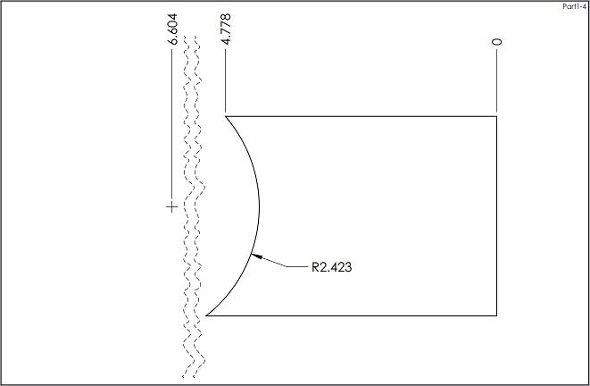
I have a radius I have dimensioned which is way off the border of the drawing, so I made the radius dimension forshortened. Then I went to dimension the center position, and it shows up way off the border, and there's no "foreshorten" display option for it. What may be the solution for this?

SolidWork Newbie since 2001
-Currently using SW2017

Inventor Newbie since 2019
-Currently using Inventor19
 
Replies continue below

Recommended for you

I don't know how to do exactly what you are asking. One work around might be to have the center location dimensioned in a reduced scale view or have the other dimensions in a detailed view.

I have to ask though, if the center location is so far off the drawing, how do you expect to measure/inspect those dimensions accurately and why are they important? Could you just dimension to the end points of the arc and the radius value? Could you use a profile of a line callout?
 
Hendersdc: Thanks for the alternate dimensioning idea. I just wanted to keep my dimensioning scheme consistent throughout, as well as consistent with other similar drawings.

SolidWork Newbie since 2001
-Currently using SW2017

Inventor Newbie since 2019
-Currently using Inventor19
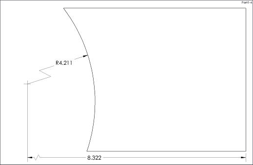
 
I am having hard time creating dimensions that are NOT forshortened:

Part1_fekmwl.jpg


"For every expert there is an equal and opposite expert"
Arthur C. Clarke Profiles of the future
 
The OP mentioned in the title that he's talking about ordinate dimensioning.
 
@Jboggs:
1. You are not OP
2. I am curious if OP could make an exception for radii dimension.
3. This is what they call "ordinate dimensions":

Capture_gow1qg.jpg


4. If OP desperately needs to use rectangular coordinates, they can be also be tabulated, or simply put next to forshortened radii center: X=..., Y=...
5. Here is yet another possibility. This one is real, but it can be simply faked:

Capture_x2r38q.jpg


"For every expert there is an equal and opposite expert"
Arthur C. Clarke Profiles of the future
 
Checkerhater: That looks great. (the December 7th post) I cant seem to make that happen. Its not ordinate but it would at least be connected, and easy to understand without fudging. How do you get the linear dim to connect to that center of the foreshortened radius.

Jboggs: Thanks for clarifying.

SBaugh: Jogging still has the center point picked way out of the border.

SolidWorks Newbie since 2001
-Currently using SW2017

Inventor Newbie since 2019
-Currently using Inventor19
 
@borsht:
To get it the way shown in Dec. 7th, I created both, radii and locating dimensions first. (There could be third - for "Y" direction)
Then I right-clicked on radii dim and picked "Display options" -->"Foreshorten".
Both dimensions become foreshortened at once.
I have 2018, but I hope it will work on your 2017 as well.
Good luck.

"For every expert there is an equal and opposite expert"
Arthur C. Clarke Profiles of the future

 
CheckerHater:
It appears I hit a nerve. If so, I apologize. It was not intentional.
"1. You are not OP"
I never claimed to be.

"3. This is what they call "ordinate dimensions":"
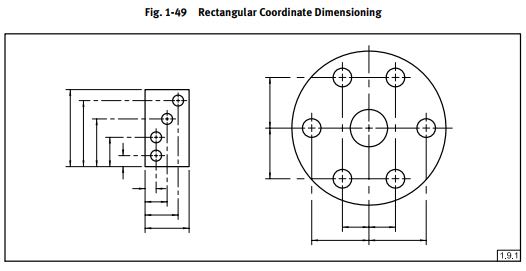
Actually your sample is not ordinate dimensioning. Here's a sample ordinate dimensioning. Most commonly used on things like large die plates with lots of holes. Preferred for those applications because it requires fewer lines, its less crowded.

"4. If OP desperately needs to use rectangular coordinates, they can be also be tabulated, or simply put next to forshortened radii center: X=..., Y=..."
I agree.

"5. Here is yet another possibility. This one is real, but it can be simply faked:"
I like your sample. Creative way to solve the problem.
 
 https://files.engineering.com/getfile.aspx?folder=5e6f05ff-4d78-4108-8382-54d81cae37e8&file=ordinate.png
Sorry for sounding harsh.
I was trying to point out that OP could consider different options (which he actually had :)), something you couldn't know for sure.
Your example is actually called "Rectangular Coordinate Dimensioning Without Dimension Lines", but the term is rarely used (I wonder why).
SolidWorks is wonderful tool, but some features are still a bit clumsy. Sometimes you have to compromise or use dirty tricks to have things your way.

"For every expert there is an equal and opposite expert"
Arthur C. Clarke Profiles of the future

 
For those clumsy tools in Solidworks go out and enter them in the top ten lists. if they make the top ten, then maybe SW will finally fix this clumsy crap that us real users have to deal with day to day.

I have been bombarding that list for weeks now. up to 33 and I have deleted 2 threads so far.

See this thread:
thread559-475974

Scott Baugh, CSWP [pc2]
CAD Systems Manager
Evapar

"If it's not broke, Don't fix it!"
faq731-376
 
Status
Not open for further replies.

Part and Inventory Search

Sponsor