Continue to Site

Eng-Tips is the largest engineering community on the Internet

Intelligent Work Forums for Engineering Professionals

  • Congratulations SSS148 on being selected by the Eng-Tips community for having the most helpful posts in the forums last week. Way to Go!

Orifice plate design 1

Status
Not open for further replies.

alienitmeca

Mechanical
Feb 20, 2014
85
Hello to all

I am new to Fluid Mechanics, I a currently trying to divide a flow into two pipes with diffrent pressure drop each, The problem I am facing is that the flow must be equally divided, so as a solution I am thinking about using an orifice plate, yet these "instrument" are generally used to mesure pressure drop, my question is as follows:

Is it possible to use an orifice plate to control the flow rate into 2 pipes?

looking forward to recieving your replies
 
Replies continue below

Recommended for you

It is possible but it is always difficult to obtain an equal split.

Perhaps you can explain what you are trying to accomplish and the tolerance in flow spilt that you would like to achieve.
 
Also how you are planning to do this physically.

Things like the length of the pipes, the relative pressures etc will make a difference.

Fluid will always want to flow down the easiest flow path so what you are actually trying to do by the sounds of it is actualy make the two systems have the same pressure drop.

Yes, orifice plates can do this, but they are fixed, so any small change in overall flow rate, density, temperature, viscosity etc will mean it will quickly go out of balance.

Can orifice plates be used to "control" the flow rate - Basically no unless everything else is fixed and doesn't change.

Remember - More details = better answers
Also: If you get a response it's polite to respond to it.
 
Thank you for your prompt replies,

I wil try to give you a discription of the piping layout and the overall system:

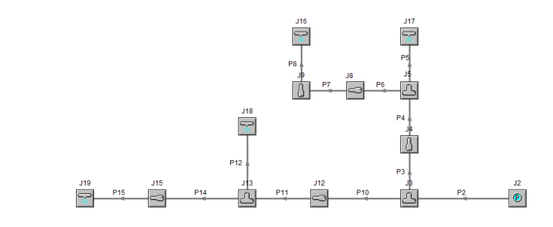
It is a fire fighting piping layout, so I have fire pumps pumping fire water into a venturi proportionner, the output fluid of the latter is foam concentrate, at the end I have 4 foam makers with the same carateristics (flow = 2000 L/min........working pressure = 5 barG), a part from the orifice plate, is there any other solution to equilibate flow in general, and specefically in my case (existing fire pumps and an already built site which restrains creating pressure drop usin regular methods such as pipe length and fittings).

Looking forward to recieving your replies
 
Flow control valve??

Still not easy to understand your layout. A sketch would help.

Remember - More details = better answers
Also: If you get a response it's polite to respond to it.
 
Using restriction orifices in fire systems is fairly common. The problem with them (as has already been mentioned) is that they are designed for a specific condition and will behave differently under different conditions. For example, your pumps have probably been sized to give 8000 L/min at 5 barg which would be the condition when all 4 foam makers have been activated. If only one foam maker is activated then the flow rate and pressure will rise above the 2000 L/min and 5 barg design values. An orifice cannot automatically adjust to this, but in the middle of a fire situation a bit of extra flow and pressure may not be a problem, provided your equipment can cope with the extra flow and pressure.

On the other hand a simple orifice, even if it does not give exactly the required flow, may be more reliable than an automatic valve that has sat unused for months or a manual valve that may have been tampered with. It depends on how rigorous your maintenance and testing program is.

Katmar Software - AioFlo Pipe Hydraulics

"An undefined problem has an infinite number of solutions"
 
Thanks for your replies, as requested, I am attaching an image of the pipie network (drawing on a flow simulation software known as AFT FATHOM)

FLOW_SIMULATION_wwq1lu.png


Hope this could help, Another question came across my mind while elaborating this simulation:

Could there be somekind of logigramme or a step-by-step method to minimize the number of iterations to be conducted in order to get the right flow in each pipe ?
I believe that someone must have thought of it !!

looking forward to receiving your replies
 
The 4 foam makers are J16 to J19?

Though I've not worked on fire fighting water supply networks before, would imagine a 5-10% variation in supply flow between J17 and J19 would be tolerable. So size the pipes such that this dp variation limit at max total flow is met? Adding an RO at J17 may also help if the line length from the supply tee to J17 to the supply for J19 is very long.
 
Start by assuming that the flow is equal to all your end points ( I assume J16 to J 19).

From J8 then work out the total pressure drop to each element. e.g. flow from J8 to J 10 is 50% of total.
Pressure are J10 is the same for both branches, but flow is 25% of total.

Do this for all branches.

Work out which one has the highest pressure drop then start to work backwards and then you will be able to see where you need to artificial pressure drop via your orifice plates.

e.g. from J 13 to J 19 (the highest pressure drop), your pressure drop is, say, 10 psi, but from J 13 to J 18 it is only 5. You know the flow, you know the pipe size, so then you can calculate an orifice size to add 5 psi to the J 13 to J 18 leg.

Do the same for the two main branches.

If only three are on then it won't work.

Remember - More details = better answers
Also: If you get a response it's polite to respond to it.
 
LittleInch, that's exacltly the problem, 4 foam makers are going to be working simultaniously according to the client because thare are feeding only one dike. After numerous simulation using the design concept you have introduced, I was able to regulate the flow with a small tolerence rate (3%), assuming the operating conditions are the same (pressure and flow rate) which I am sure that it won't be that perfect when running our system in real life.


Good, glad it worked out. 3% in reality is not achievable - most of the simulations aren't that accurate, but it will get you a lot closer than not having any modifications.

Remember - More details = better answers
Also: If you get a response it's polite to respond to it.
 
I apreciate your help, all of you whom contributed to this thread. Hope it has been as much informative to you as it has been to me

BIG THANKS TO ALL
 
Status
Not open for further replies.

Part and Inventory Search

Sponsor