Eng-Tips is the largest engineering community on the Internet

Intelligent Work Forums for Engineering Professionals

  • Congratulations waross on being selected by the Tek-Tips community for having the most helpful posts in the forums last week. Way to Go!

OSHA Guardrail 3

Status
Not open for further replies.

cal91

Structural
Apr 18, 2016
294
0
0
US
I'm checking a 3/8" Ø aircraft cable to be used for guardrail and lifeline during construction. Everything is checking out, except for the 3" max deflection requirement for guardrail found under OSHA 1910.29(b)(4)

"When the 200-pound (890-N) test load is applied in a downward direction, the top rail of the guardrail system must not deflect to a height of less than 39 inches (99 cm) above the walking-working surface."

The guardrail is at 42" so 42"-39" = 3" deflection.

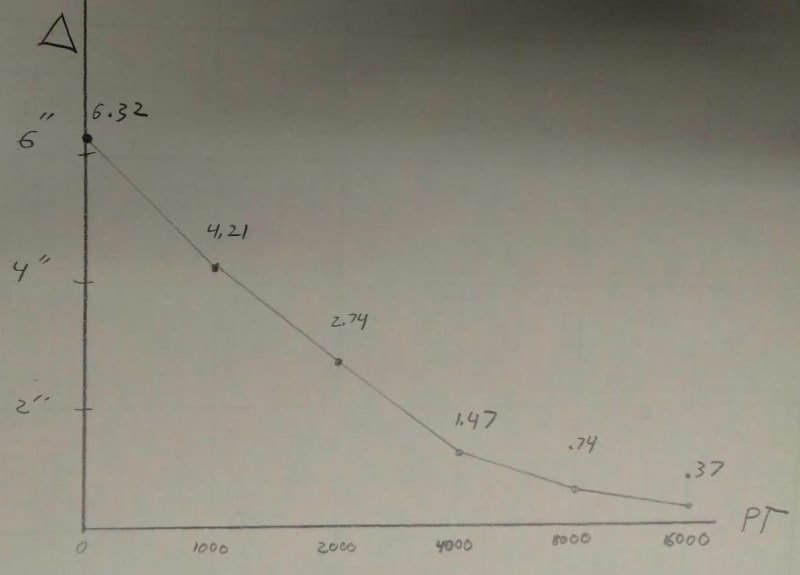
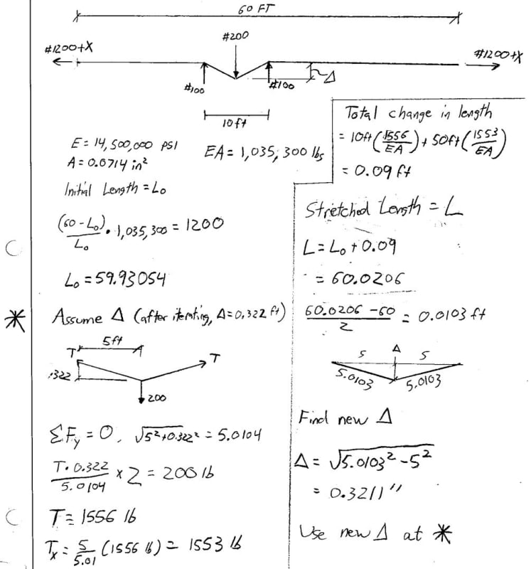
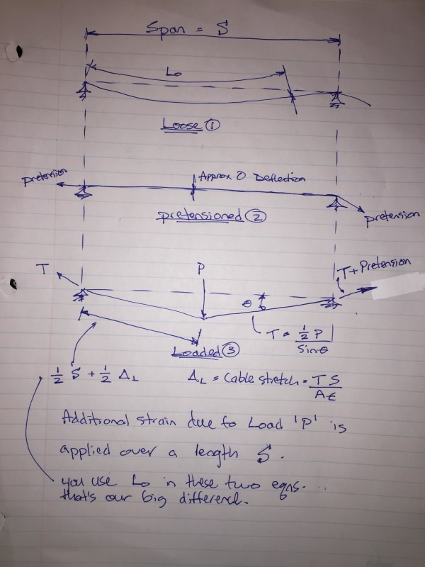
With the stretch in the line accounted for I'm getting that I can't have more than an 8 foot length of cable between anchorages, which is impractical. I also know that this cable is used all the time as guardrail for up to 120' between anchorages. I am trying to get this to work for up to 18'0" spans and up to 120'-0" between end anchorage. But that case gives me 12" of deflection even though strength works out.

Just wanted to pick the brains of you fellow eng-tippers (is that what we're called?) about this situation. Do I not even need to apply this requirement since it's only for construction and not permanent?
 
Replies continue below

Recommended for you

I've been on construction sites where we've used cable as a handrail. Couldn't tell you spans for certain but they definitely weren't 18'. The cable was also tensioned to take out all the slack. Whatever you decide on deflection, 12" is in no way reasonable for guardrail.
 
Even if I put something reasonable in, say an 8'-0" span and 60' total length between anchorages, the deflection from 200 lbs is about 5.5".
 
If you're tied off to it, then I wouldn't classify it as a guardrail, I would classify it as a life-line. A guardrail would be in place for a situation where you're not tying off.
 
Taken directly from OSHA's website: Wire rope and/or cable as a method of perimeter protection for a building under construction.

The use of wire ropes as top rails and intermediate rails of guardrail systems used for perimeter protection or for guardrails used on scaffolding meeting the equivalent requirements of 29 CFR 1926.500(d)(1) and 29 CFR 1926.451(a)(5) is acceptable provided it meets the following guidelines:

(1) Wire rope shall be secured to each support and taut at all times.
(2) The wire rope shall be free of sharp edges, burrs, or projections which may be a hazard.
(3) The maximum deflection of the top rail when a load of 200 pounds is applied in any direction at any point on the top rail shall not exceed 3 inches in one direction which includes the free hanging sag in the wire rope.

Our compliance officers are aware that wire rope is an acceptable method of perimeter protection for buildings under construction. If we can be of further assistance, please let use know.

Sincerely,

John B. Miles, Jr., Director
Directorate of Field Operations

 
You will need to look at increasing the cable pretension to satisfy the 3" deflection limit at those spans. Take a look at this article which is written for vehicle barrier cables but can be adapted to your situation: Link.
 
Thats exactly what I ended up doing. I put a maximum total length of 60'-0", maximum span of 10'-0", and had them add 200 pounds of pretension for every 10'-0" of cable length. That solved the issue. Thanks guys!
 
Cal91, I have a spreadsheet written for multispan cable handrails and safety lines so I checked your 6 x 10' spans with 1200lbs total pretension. I have a total of 6.5" sag with a 200lbs point load. Thats based on 3/8" diameter cable, effective area of 0.6xA[sub]gross[/sub], and an effective modulus of 14.5x10[sup]6[/sup] psi.

I checked the results with the gross area of the 3/8" cable and 29x10[sup]6[/sup] psi and I get about 4.25" sag. Curious if you used these values in your calculations. From what I've read the typical "fill factor" for wire rope is 0.6, and effective modulus about half of steel which accounts for some rotation in the wires which lengthens the cable.

I played around with the pretension as well. The pretension drives the initial shape of the cable which determines the initial length of cable and the initial shape when loaded (before considering the change in strain). The final sag is then determined using the change in strain, and change in length (iterative process). This means that once your pretension brings your cable taught (essentially no initial sag) increasing your pretension has no appreciable effect on the final sag. Using your 6x10' setup as an example - with 1200lbs pretension I get initial sag of 0.03" in each span, final sag of 6.47" and loaded cable tension of 2130 lbs. With 200 lbs of pretension I get initial sag of 0.18", final sag of 6.49" and loaded cable tension of 1130 lbs. So beyond a certain pretension you're doing more harm than good.

There are a couple other things to watch for in safety cables - if you have a long run of cable that is used year round, the difference in temperature from install to time of use could effect the max sag and max tension. And if your anchor points aren't completely rigid, then you could increase the loaded sag as well - if you're anchored to a flexible post, this should be taken into consideration.
 
CANPRO,

I appreciate the response. I used 0.65 * Area and 0.5* Modulus and got a deflection of 3.84" under a pretension of 1200 lbs. I (respectfully) do not agree with your statement that increasing pretension has no appreciable effect on the final sag. Increasing a member's tension increases the member's transverse stiffness (this increased stiffness is ignored in 1st order analyses but accounted for in 2nd order analyses).

Holding these variables constant...

A=.0714 in2
E= 14,500,000 psi
P = 200 lbs
Total distance between end anchorages = 60 ft
Length of loaded span = 10 ft

And changing pretension I get the following:

PT=0 lb, Δ=6.32"
PT=300 lb, Δ=5.70"
PT=600 lb, Δ=5.00"
PT=900 lb, Δ=4.40"
PT=1200 lb, Δ=3.84"
PT=1500 lb, Δ=3.38"
PT=1800 lb, Δ=2.98"

One false assumption I have is that the rope is weightless. Is this something that cannot be ignored?
 
There is deflection due to self weight that must be accounted for. And a large portion of the pre-tension goes into removing that slack out of the cable. That's why Canpro indicates it's a diminishing return by increasing the the pre-tension.
 
I would just add the selfweight of the cable as a lumped load at the middle with your 200 lbs on the span in question... should be conservative to neglect it elsewhere on the other spans as it will have the effect of increasing tension on the wire on the loaded span. I don't think you'll see much effect though, it's only a couple pounds of wire. This isn't like power poles with no pretension spaced at 50 feet or whatever.
 
cal, I may very well be wrong the about the limiting pretension - and if I am, I would very much like to understand why. Could you please elaborate on the tension increasing the transverse stiffness? I could see maybe that by increasing the pretension that you bring your effective modulus closer to the full value for steel.
 
It's not so much bringing your effective modulus closer to the full value of steel, although that may happen as twisted wires become more straight.

It's in the geometry of the displaced member. A horizontal tensile force in a displaced cable has a vertical component that resists the applied force, so increasing that tension means less displacement needed to resist the transverse force.

I imagine it as if your cable system is fixed at one end, and you've got the Hulk pulling the cable on the other end. If there's 200 lbs on one of the spans, it will deflect a certain amount. The Hulk can pull the rope even harder to decrease the deflection. As the deflection approaches 0, doubling your applied tension will halve your deflection. As the deflection departs from 0, you need less than double your applied tension to halve your deflection.
 
cal91 said:
A=.0714 in2
E= 14,500,000 psi
P = 200 lbs
Total distance between end anchorages = 60 ft
Length of loaded span = 10 ft

Add to that, the pretension and the weight of the cable, is there anything else required? Is the P=200 horizontal? and due to a normal point load straight line deformation? based on frictionless supports and total strand length? The strand deflection based on a maximum span catenary vertically and the deflection based on the root of the sum of their squares? or, do you have to assume the P can be downward too.

I've not been involved with the design of safety cables, but, looks like an interesting project.

Dik
 
Cal, I very much appreciate you pointing out that you respectfully disagree with me. I've always found respectful disagreements to be very productive.

With that said, I respectfully disagree with your statement that doubling the pretension will halve your deflection. I was on board with the Hulk analogy until that sentence. In fact, the numbers you posted support my argument - every 300 lbs increase in pretension produces less and less reduction in deflection...if you extend your data set to higher pretension, I strongly suspect that you'll reach a limit on how much you can reduce your deflection. This happens because once you essentially take all of the sag out of the unloaded cable and it is taut, the total unloaded length of cable (between two fixed supports) is not going to change much at all by increasing the pretension. Since the unloaded shape (and total length) is essentially the same for the increased pretension condition, so is the initial loaded shape of the cable once the load is applied. And if the initial loaded shape is the same, then so is the additional strain imparted on the cable - therefore the same additional stretch - therefore the same loaded deflection.

The simple way in which I picture this "pretension limit" is that as you attempt to reduce the deflected shape, you're increasing the additional tension in the cable due to the applied load - which increases the strain the cable, which increases the sag. This creates a self-limiting effect on the deflection reduction.

I think we're actually fairly close on how we approached this problem, and I'm interested to see what the difference is...so if you don't mind, bear with me while I quickly layout my process for solving this problem. To simplify, I'll describe my process for single span:

- Define cable properties and distance between supports
- Start with a defined pretension
- With a defined pretension, calculate the mid-span deflection in the unloaded condition
- With the unloaded deflection, approximate the actual length of cable
- With the load applied mid-span, assume the loaded shape is a straight line from each support to the applied load. Using the
initial length of cable to define the geometry of the triangles, the tension in the cable and support reactions can be determined
- Using the tension in the loaded cable, calculate the additional strain applied to the cable, and the associated stretch
- Using the new length of cable, re-draw the deflected shape. Since the shape changed, so do the forces in the cable and so do the strains. This is an iterative process that is automated in excel.

It took me a while to wrap my head around this, especially with multiple spans. I find it best to think in terms of strain when solving these problems.


CANPRO,

Thanks for the discussion. Our processes are just a bit different (the main difference being you account for self weight, I believe it to be insignificant and acceptable to ignore.) I bolded where what I do is different.

- Define cable properties and distance between supports
- Start with a defined pretension
- With the known pretension, calculate the actual length of cable (will be slightly shorter than the length between anchorages because of strain due to pretension)
- With the load applied mid-span, assume the loaded shape is a straight line from each support to the applied load. Assume a preliminary deflection to define the geometry of the triangles, the tension in the cable and support reactions can be determined
- Using the tension in the loaded cable (which is found from static equilibrium), calculate the additional strain applied to the cable, and the associated stretch. This will give you a new deflection.
- Using the new length of cable, re-draw the deflected shape. Since the shape changed, so do the forces in the cable and so do the strains. This is an iterative process that is automated in excel.

I agree with most of what you say, but I'm sticking to my guns that as deflection approaches 0 (or pretension approaches infinity) doubling your pretension halves your deflection. This is because the point load becomes less significant as pretension increases so it approaches an inverse relationship.

And the numbers I provided do support that. Every 300 lbs added has less TOTAL affect (because there's less deflection to halve), but every doubling in force gets closer to halving the previous deflection. I made a graph to show this. (These numbers use the same preliminary information as my previous numbers)

I do agree that eventually, adding pretension provides diminishing returns (towards the end of the graph adding 8000 more pounds reduces the deflection by 3/8").

It's been a good discussion, and I appreciate your input CANPRO.

Capture_ohhrsl.jpg


6.32/4.21 = 1.50
4.21/2.74 = 1.53
2.74/1.47 = 1.86
1.47/0.74 = 1.99
0.74/0.37 = 2.00
 
cal, I apologize, I took your statement about doubling the pretension and halving the deflection too generally...of course you had specified that this is the case at relatively higher pretension - my response indicated that you meant this is the case for all levels of pretension. Both of our methods show the same trend as pretension increases.

I account for the self-weight just because I built a general spreadsheet, and sometimes it is significant. If the self-weight is truly insignificant than it shouldn't make a difference whether you include it or not...in this case I don't believe it makes a difference.

I think this is the biggest difference in our results --> "calculate the actual length of cable (will be slightly shorter than the length between anchorages because of strain due to pretension)". I've been trying to wrap my head around this. Are you saying that if you have 60 ft between anchorages, that you consider your initial length of cable to be less than 60 ft?

The way I look at the initial cable length is this - you set the pretension, and then you can determine the initial sag using statics. Once you know the sag, the initial length of the cable is purely a function of geometry. From there I consider the additional strain imparted on the cable from the applied load. The initial strain from the pretension only comes back into play at the end of the calculation when I add the pretension to the additional tension from the applied load.

Agreed this has been a good conversation. And I don't mean to drag this on - but from reading this and your previous posts, I get the sense that you are a good engineer...and I've been using my spreadsheet for a couple years now and our results are far enough off that I would like to iron out any mistakes I may have been making.
 
I appreciate it CANPRO. And no need to apologize. I've found that disagreements on this forum are often just a result of difficulty in communicating highly technical ideas without the advantage of being in person, talking in real time with the aid of sketches, etc.

CANPRO said:
I think this is the biggest difference in our results --> "calculate the actual length of cable (will be slightly shorter than the length between anchorages because of strain due to pretension)". I've been trying to wrap my head around this. Are you saying that if you have 60 ft between anchorages, that you consider your initial length of cable to be less than 60 ft?

Exactly. Again, I'm ignoring self weight. So there is 0 deflection when there is no load. A 60 ft length rope anchored at 60 ft will have 0 strain, so 0 pretension. A 59.9 ft rope anchored at 60 ft has a strain of 0.1 / 59.9 = 0.00167, and the pretension force is EA * 0.00167.

The way I look at the initial cable length is this - you set the pretension, and then you can determine the initial sag using statics. Once you know the sag, the initial length of the cable is purely a function of geometry. From there I consider the additional strain imparted on the cable from the applied load. The initial strain from the pretension only comes back into play at the end of the calculation when I add the pretension to the additional tension from the applied load.

Depends on what we are defining as the initial length. Is it the unstretched (zero strain) length? Or is it the length after pretension is applied, including sag from self weight, but before the point load is applied?

If it is the latter, then this might be where our differences stem from. I believe you will be getting overly conservative results if, for your base 0-strain length, you are using the length after pretension and sag due to self weight. Again, it's difficult to communicate with only text so I've provided an example hand calc that shows step by step of how I solve this problem.

Capture_saowgd.jpg
 
cal, agreed that this is our fundamental difference, we're considering different lengths of cables. Sketches do help a lot, I've attached one that shows how I see the basics this problem.

The way I see it, the additional strain from the applied point load is applied over the pretensioned length of cable (essentially 60ft in this case). So when considering the additional stretch in the cable due to the point load, I think it is best to consider the actual length of the cable based on the pretensioned shape of the cable.

This is a bit of a tricky design...yes, maybe one method is conservative for the deflection, but you'll underestimate the tension in the cable.

cable_rkexkg.jpg
 
Status
Not open for further replies.
Back
Top