Continue to Site

Eng-Tips is the largest engineering community on the Internet

Intelligent Work Forums for Engineering Professionals

  • Congratulations GregLocock on being selected by the Eng-Tips community for having the most helpful posts in the forums last week. Way to Go!

Out-of-plane Eccentric load on bolted group

Status
Not open for further replies.

Belisario_G

Mechanical
Jun 22, 2017
9
Hi peeps,
This frame will be bolted on the ground. The load applied is shown by the red arrow, my question is how to deal with this loading type. Can anyone recommend an analysis method for the bolts ? I know the bolts are undergoing shear force and bending moment (out-of plane), but I'm not familiar with real life approaches to this problem (Steel code etc.).

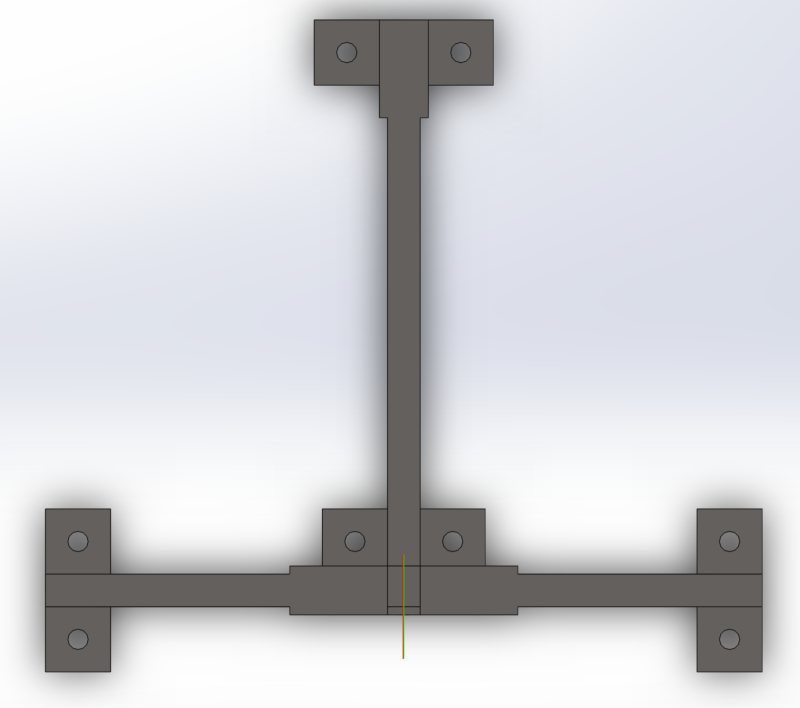
Attached are some views to this structure
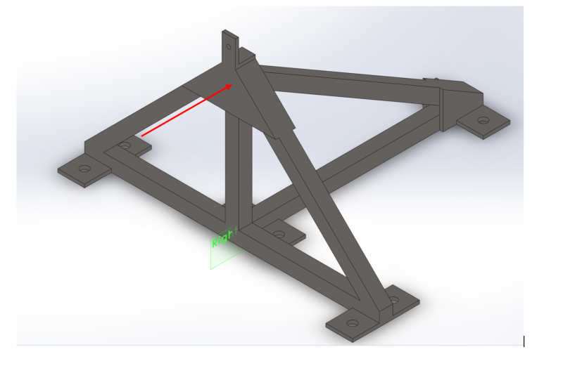
Frame1_qxo5tu.png

TopView_Bolted_zo6mjq.png
 
Replies continue below

Recommended for you

Well basically bolts should not get bending moments
Bolts a good for shear and tension...but not bending

Then you should go see an structural engineer near you :)


best regards
Klaus
 
Agree with others, no bolt group moments. You'll have moments on the frame that will be resisted by tension/compression couples involving tension on the bolts. So just shear and tension.

I like to debate structural engineering theory -- a lot. If I challenge you on something, know that I'm doing so because I respect your opinion enough to either change it or adopt it.
 
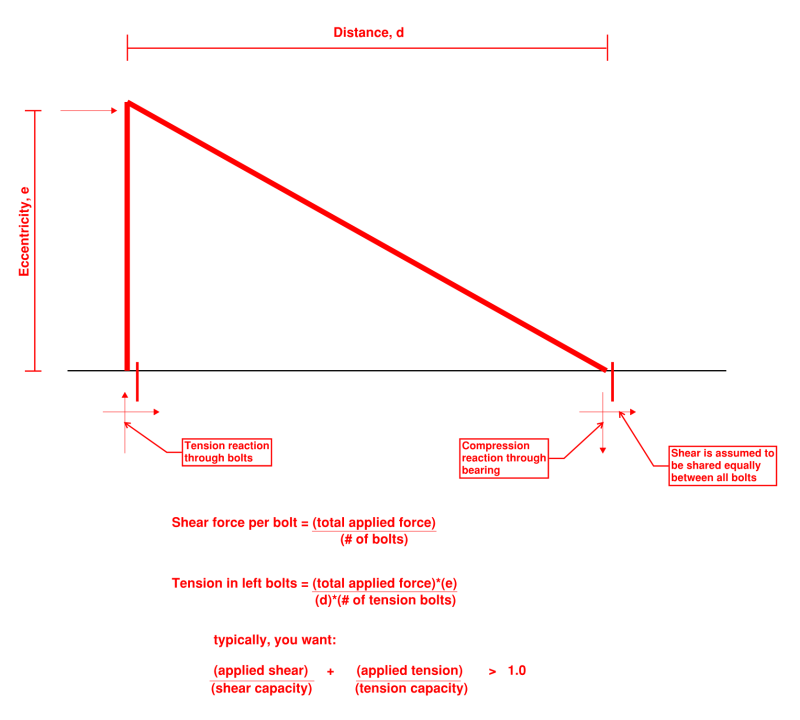
Sorry, that last inequality should be less than or equal to (not greater than).
and the shear reactions should be pointed left, not right.

I was in a hurry!
 
DETstru - For your equations, would you mind giving me your source? I'd like to see the formulations to those equations.

Thanks for your help and thanks to all for the feedback and replies.
 
Belisario_G, the sketch and equations by DETstru are very good. The equations are essentially just statics and geometry.

I'm not sure whether you are familiar with concrete code procedures for checking capacities of bolts embedded in concrete (I've been presuming concrete base when you mentioned "ground", but please let me know if I'm mistaken). The relevant code is ACI 318-14, there are some long, convoluted equations for determining capacity, checking a few different failure modes. There are some simple software programs that aid this. But the upshot is that in these scenarios, the potential breakout of anchor bolts from the concrete almost always governs over the actual capacity of the bolt steel.
 
Belisario_G, the equations are based on simple statics. Any statics textbook will have this sort of thing.

The load, call it "P", acts above the surface at an eccentricity, "e", parallel to the plane of the surface. This creates a moment equal to P*e.

The shear is resisted by the bolts by sharing the load equally among them. So you divide P by the number of bolts to determine the shear in any bolt.

The moment is resisted by tension in the front bolts and compression in the back bolts. Typically the back bolts don't transfer the compression, the frame bearing against the surface does the work. For the front bolts, they are in tension. The resisting lever arm is the distance "d". So you divide the moment, Pe, by "d" to get the tension in the bolts. Then you divide that by the number of bolts in the front since you assume they share that tension load equally.


Once you find the tension and shear in those front bolts, you compare that to the capacity of whatever bolts you choose to use. Let's say:
the shear reaction is 2000 lb. and the tension reaction is 1000 lb.
the shear capacity of your selected bolt is 3000 lb. and the tension capacity is 2000 lb.

In shear, the demand/capacity ratio is 2000/3000 = 67%
In tension, the demand/capacity ratio is 1000/2000 = 50%

Adding these together gets you 67% + 50% = 117%
The bolts are over capacity and you must use a different bolt.
 
Nor Cal SE - The frame is mounted on a stationary steel plate.

For calculation purposes I am referencing the link posted on this thread (My question is if it would be suitable to use a static failure theory (Von Mises) to predict the factor of safety of the bolts ? The loading conditions of this problem have been established to be a direct shear and tensile/compressive force due to the bending moment.
 
4 bolts (on the A frame) react the tension half of the couple reacting the off-set moment. you could add a moment to these bolts, but that'd appear as a couple rather than bending on the bolts; then, sensibly, there's be a small shear reaction too.

the pad reacts the compression half of the couple.

the shear is reacted by either the 2 bolts under the diagonal, or by the 4 bolts (on the longitudinal member).

another day in paradise, or is paradise one day closer ?
 
One other wrench to throw in this is the need to check prying effects on the bolts (given how the frame is being connected to the stationary steel plate). If your base plates are too thin (specifically for the tensile loaded portion of the frame), the equation DETstru stated may not be conservative unless you account for the reduced tensile capacity resulting from prying effects. Easy fix is to use thicker plates. AISC has design equations that can help determine a suitable plate thickness.
 
MGaMart can you provide a reference for those AISC standards?
 
I only have up to the 3rd ed of the manual, but it's found on p 9-10 (perhaps someone with the most recent version can provide that page number). A quick Google search turned up this spreadsheet that is used for T sections in prying. Given your pictures, it looks as though that frame is made up of HSS sections? If so, I'd use AISC Design Guide 24 (Section 5.5). Alternatively, if you're Canadian like me, CIDECT Design Guide 3, (p 85) also provides prying action procedures for HSS sections with bolts on two sides only.
 
 http://files.engineering.com/getfile.aspx?folder=144d3ec8-f5ed-479c-b8e4-a0cca5df094b&file=PRYING9.xls
good find ! a little conservative ...

prying reaction is at the tip of the flange ... triangular distribution is a less conservative option.
in the example the flange is nearly thick enough to neglect prying, but the "full" prying load is applied ... maybe some reduction in prying due to stiffness of flange ??

another day in paradise, or is paradise one day closer ?
 
Status
Not open for further replies.

Part and Inventory Search

Sponsor