Continue to Site

Eng-Tips is the largest engineering community on the Internet

Intelligent Work Forums for Engineering Professionals

  • Congratulations IDS on being selected by the Eng-Tips community for having the most helpful posts in the forums last week. Way to Go!

Out of plane moment (lateral force)

palk7 EIT

Structural
May 12, 2020
150
Hi,

It might be a basic question but just wanted to run it by for clarification.

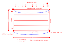
The roof diaphragm runs north south in the attached image and the chord members are W beams in (tension and compression), the deck is attached to these beams.

From the diaphragm moment and diaphragm depth calculated the tension and compression forces on these W chord members, however should I also have to check for the out of plane moment 24.86 kip-ft (due to lateral load) and deflection on these W beam chord members, I don't think so but just looking to confirm the same.

Thank you
 

Attachments

  • image001.png
    image001.png
    61.4 KB · Views: 24
Replies continue below

Recommended for you

Let me know if I understand your question correctly.

You broke down you moment 24.86 kip*ft into a tension compression force of 1.65 kip. Do you need to consider the 24.86 kip*ft any more?

If this is correct, then no, you do not need to consider the 24.86 kip*ft any more for the design of the W beam chord members.

One quick item on verbiage as well, I would not call this an "out of plane moment", I would call this diaphragm moment an "in plane" moment. Out of plane moment would be like a basement wall bending about it's smaller axis due to lateral earth pressure.
 
That's correct broke down the in plane moment of diaphragm into a comp. Force of 1.65 kips. On the chord member. So in this case the in plane moment need not be checked on the minor axis of the W beam chord ? Right
 
If I take a step back and put it this way maybe it will clear things up. Hypothetically, if you sized the beam for the 24.86kip*ft, would you need the diaphragm at all? The beam would be sized to resist the lateral loads and could transfer it to your side walls, leaving you with no reason to have a diaphragm (aside from holding gravity loads of course).

The diaphragm is basically a deep beam, where the W shapes are the top and bottom flange and the deck is the web. When sizing a W beam for gravity loads do you check the top and bottom flange to support the moment by itself, or is it the composite shape that bends, with tension/compression stresses building up on each side of the elastic (or plastic) neutral axis?
 
Last edited:
Since you have a diaphragm, the 24.86 k-ft moment is not acting on the W-beam. The W-beam only sees the chord force.

You would want to check chord forces, although most people may not check chord forces after having enough experience and seeing how small the forces are.

You should look at the gravity moment in the W beam, and the compressive chord force (1.65k). Make sure that the interaction of the moment and compressive force do not exceed the beam's capacity.
 
EngDm, that could be done too but the deflection in minor axis of beam would be huge for a 35 feet span isn't it.
 
Since you have a diaphragm, the 24.86 k-ft moment is not acting on the W-beam. The W-beam only sees the chord force.

You would want to check chord forces, although most people may not check chord forces after having enough experience and seeing how small the forces are.

You should look at the gravity moment in the W beam, and the compressive chord force (1.65k). Make sure that the interaction of the moment and compressive force do not exceed the beam's capacity.
Only thing to consider, if you are relying on the beams as well as your perimeter deck angle for diaphragm deflection, then the connections of beam to column needs to be designed for the axial load as well. If you are relying on the continuous deck angle by itself then you don't need to do this.
 
EngDm, that could be done too but the deflection in minor axis of beam would be huge for a 35 feet span isn't it.
Yes it would be, especially in the weak axis, and thats why we use diaphrams. I just used that as an example. You've already resolved the moment into component forces, so you don't need to design the components for the moment. Deck is designed to pick up the shear/shear flow, the W beams are chord to pick up the resolved axial tension and compression.
 
however should I also have to check for the out of plane moment 24.86 kip-ft (due to lateral load) and deflection on these W beam chord members

This has never before occurred to me but I think that your concern is legitimate.

In answer to your question:

1) To my knowledge, nobody does consider that weak axis moment.

2) The weak axis moment will certainly materialize to some degree. Wherever the diaphragm moves, the beam moves.

I suspect that, investigated in detail, this effect would get lost in the noise of the other design actions and the various load casing. That said, I've not investigated this in detail so I guess I don't know for certain.

Thanks a lot. Now I'll have to turn a blind eye to even more stuff...

This is quite similar to the design of truss top chords prior to commercially available FEM. Truss chords pick up some moment by exactly the same reasoning, particularly if the chord stiffness is large relative to the truss depth. And we didn't sweat that for the most part until FEM came along. Or, stated more hopefully, we ensured truss proportions that would tend to obviate the effect.
If you want even more to worry about, pretend OP's picture has several intermediate columns. Now each of those beams has a p-delta on the compression strut force since the columns get more and more deflected as you go towards the middle of the diaphragm.
 
Yes I'd totally agree with KootK here -
Any deformation of a structural element - in this case a resulting curvature of the chord beams - implies bending stress in addition to the axial chord forces.

But the beam isn't taking all the load - rather it is performing as a part of the overall "horizontal beam" that you chord-deck-chord assembly is providing.

So if you can properly model the overall stiffness of the entire system and apply the lateral load - you will get a deflection "x" in the system - the chords will bend in flexure and the deck will distort under primarily shear deformation. Once you know "x" you can back calculate the bending in the chords.

As with KootK - I suspect the bending is small and essentially inconsequential.
 
My only additional thing to add would be about detailing and load path. How is this lateral load getting in to the diaphragm? If the beam is loaded near the top flange and the top flange is fastened regularly to the deck than the load will go straight to the diaphragm and the chord axial load checks are appropriate. If the beam is loaded at the bottom flange which is braced say at 6 ft intervals by kickers than the beam would see some weak axis bending (and maybe some torsion) between the kickers. Other load paths are possible, but the perimeter detailing has to be considered.
 

Part and Inventory Search

Sponsor