Continue to Site

Eng-Tips is the largest engineering community on the Internet

Intelligent Work Forums for Engineering Professionals

  • Congratulations KootK on being selected by the Eng-Tips community for having the most helpful posts in the forums last week. Way to Go!

Out of plane moment on circular pattern bolt 3

Status
Not open for further replies.

DoubleStud

Structural
Jul 6, 2022
453
I came across this video. It is quite interesting. After he did all of the integrations, he ends up getting equation of tension force for a bolt in term of Moment, Pi, Radius and thetas (see video minute 9:43). I was just wondering, is there a reference book somewhere that uses this equation? I want to use this equation to calculate the highest tension bolt on a round pole base plate.

 
Replies continue below

Recommended for you

Few things off the bat:
The derived formula relies on the neutral axis being known. You’ll need to solve for this somehow.
This may not be applicable to a base plate as you’ll have either a triangular or rectangular compressive stress block for the bearing.

The general setup for the integrals is similar so you could use that as a basis for working out a numerical approach in excel.

See this document by Bentley: Link

Here is a spreadsheet I made that implements the method described in that white paper with some corrections:Link
(The sheet is polygons so you’d need to approximate a circular plate/opening with straight segments)
 
Celt83, my head is about to explode. If I do case 1 from SCM, I need to do trial and error to find the NA. But the effective width of the compression block is not constant because it is circular. Assuming the NA is in the middle is conservative? Is it too conservative?
 
DoubleStud said:
Assuming the NA is in the middle is conservative?
Can’t say for sure if it would be conservative or not, but if the computed forces for bearing compression and anchor tension are not in static equilibrium with the applied loading then I’d say the analysis likely contains significant error.

I relearned some calc 2 and calc 3 a bit ago to work out some of the math in the spreadsheet I posted. For a circular plate the integrals are “easier” if you look at things in polar coordinates.

This guy has full lectures for all three levels of calculus on youtube: Link
 
Mr. DoubleStud (Structural)

I watched the subject video .

My points are,

-IMO , the assumption of Neutral Axis at center is not reasonable for flanged joint bolt load calculation . This method ( The assumtion of section modulus W=( Π*D**2)/4 ) is used for storage tank anchor load calculations ..

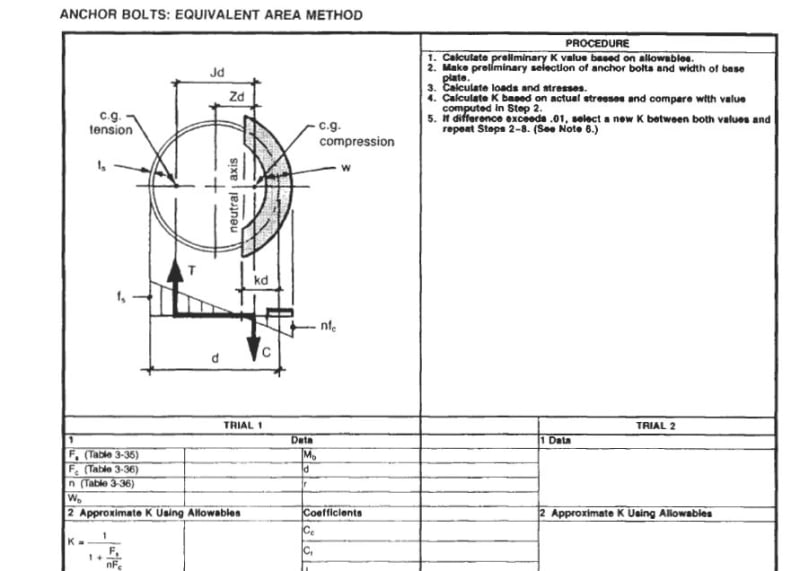
- ASME uses the equivalent equivalent area method ( the basis of design is compression ring at at compression side of NA axis and discrete tension elements at tension side )

- The excerpt below is equivalent area method , from ASME model.

Equivalent_area_method_qgwfi8.jpg


- The equivalent area method for your case would differ acc. to base plate ( circular, square etc..)

- Suggest you to look to the following doc.


Tim was so learned that he could name a
horse in nine languages: so ignorant that he bought a cow to ride on.
(BENJAMIN FRANKLIN )

 
TLDR. You had me at doing integration to solve the load on a set of bolts. As noted above there are many solution paths, many different assumptions; I prefer a simple "bolt group".

"Hoffen wir mal, dass alles gut geht !"
General Paulus, Nov 1942, outside Stalingrad after the launch of Operation Uranus.
 
With large diameter bolt circles, is there any sort of 'shear flow' that interferes with the bolt loads? If so, how is this addressed?

-----*****-----
So strange to see the singularity approaching while the entire planet is rapidly turning into a hellscape. -John Coates

-Dik
 
My quick & dirty check for bolt forces on flanged plates or round baseplates is like the Horn document (p63) linked by HTURKAK.

T = Mc/I

Where:
c = BC/2 (for max bolt force)
I = (n * BC^2)/8 (simplification of the I calculation presented by Horn)

This assumes neutral axis at center and an elastic distribution of bolt forces.

 
and an SMath solution (checked, using an Excel spreadsheet). No shear flow alteration (not known how to address this, easily):

[URL unfurl="true"]https://res.cloudinary.com/engineering-com/image/upload/v1672715723/tips/Bolt-Circle_nqdqbc.pdf[/url]

[URL unfurl="true"]https://res.cloudinary.com/engineering-com/raw/upload/v1672715723/tips/Bolt-Circle_qr2qwq.sm[/url]

-----*****-----
So strange to see the singularity approaching while the entire planet is rapidly turning into a hellscape. -John Coates

-Dik
 
Hey dik,

I was just looking at how you predefine a lot of your inputs in matrices so that you can easily choose material properties and things when you're doing the calc. Have you looked at using the combobox plugin to make the choices easier? It will take a matrix as input, and populate a drop down box with the strings in the column from that matrix. You can then just select from a pulldown list when you're doing an individual calc and the control will assign the index of the option you picked to a variable. It feels pretty slick when you get it set up right and looks like it would fit right into your workflow.

 
Combo box works OK... just don't use it because a lot of this stuff is cut and paste... I think combo boxes look slicker... I'll take a gander at it again.

-----*****-----
So strange to see the singularity approaching while the entire planet is rapidly turning into a hellscape. -John Coates

-Dik
 
An out-of-plane moment on a circular pattern bolt refers to a bending moment that is applied perpendicular to the plane of the bolt. This type of moment can cause the bolt to experience torsional or shear stress, which can affect its ability to withstand the load.
There are a few factors that can influence the out-of-plane moment on a circular pattern bolt:

Bolt size: Larger bolts generally have a higher resistance to out-of-plane moments than smaller bolts.

Bolt material: The material of the bolt can affect its resistance to out-of-plane moments. For example, a bolt made of a stronger material such as high-strength steel may be able to withstand higher out-of-plane moments than a bolt made of a weaker material.

Bolt orientation: The orientation of the bolt in relation to the applied moment can also influence its resistance to out-of-plane moments. For example, a bolt that is oriented perpendicular to the moment will experience less stress than a bolt that is oriented at an angle.

Load: The magnitude of the applied out-of-plane moment will also influence the bolt's resistance to this type of stress.

To ensure the stability of a circular pattern bolt under out-of-plane moments, it is important to consider these factors and select a bolt that is appropriate for the specific application.

 
"An out-of-plane moment on a circular pattern bolt refers to a bending moment that is applied perpendicular to the plane of the bolt. This type of moment can cause the bolt to experience torsional or shear stress" ... umm, ?? out-of-plane moment will put apply tension/compression loads to the bolts (if loaded by pure moment). If loaded by an offset shear, then of course there'll be shear loads (to react the shear) but the moment will be reacted by tension and compression.

"Hoffen wir mal, dass alles gut geht !"
General Paulus, Nov 1942, outside Stalingrad after the launch of Operation Uranus.
 
Status
Not open for further replies.

Part and Inventory Search

Sponsor