Eng-Tips is the largest engineering community on the Internet

Intelligent Work Forums for Engineering Professionals

Out of plane stability of truss chord supported by 'wind-posts' 1

Status
Not open for further replies.

jaskamakkara

Structural
May 27, 2020
35
0
0
FI
Hi guys,

I have a small indoor truss that's designed to support a short bridge that will withstand basic foot traffic. The truss is to be hidden inside a wall, and since there is no lateral restraint or returns to the wall along it's 13m span, I need the steelwork to support any lateral loads that the wall will encounter (people leaning on it, whatever). My main concern is with the out-of-plane buckling of the compression chord of the truss, since it's 13m long and there's nothing to brace it back to. I have put in some 'wind columns' which are just continuations of the vertical truss members up to the next floor of the building where they are laterally (but not vertically) supported - the idea being that these will take the lateral loads in bending, and also restrain the compression chord of the truss. Now, my question is, can I reasonably assume that these wind posts are laterally restraining the compression chord of the truss? Obviously, for the chord to buckle it would have to bend these wind posts, but I am unsure how to quantify the amount of restraint they provide. The wind posts are, at their bottoms, supported by the axial stiffness of the small floor beams that are tied back at their other ends either to a stiff beam HEB220 - so very stiff in it's minor axis - or fixed into another wall.

Hopefully this is clear, the picture below should help:

Capture_c94xu1.png


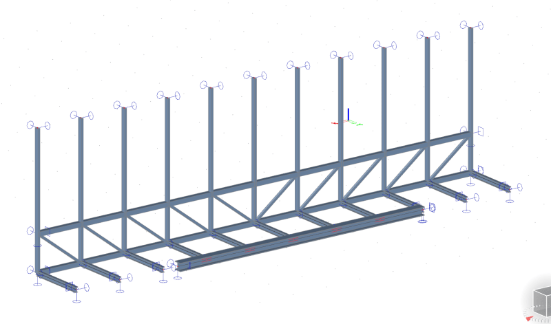
Any help would be appreciated!
 
Replies continue below

Recommended for you

Oooh. Another fun buckling question! And once I got my head around your question you didn't do too badly explaining it here either. [smile]

Short part-answer. I would suggest that your need to employ a rational buckling analysis approach. Forget about simple effective lengths, it is going to be far more complicated. You need to delve deep into the stiffness of the wind columns including the effect of their deflection on the truss when loaded by wind. You have compounding P-delta effects.

Normal provisions in codes often just deal with this issue with the restraining element required to designed for handle 2.5% of the axial load or similar. But this is just a fudge and would be unconservative in this situation. The way I would approach this problem is to let the my structural modelling package do the heavy lifting with a decent amount of intelligent rational analysis behind it. The effective length of the compression cord is dependent both on the stiffness and the loading of your 'wind columns'.

Other people here are far more clever than me though so will hopefully be able to more readily explain their approach from first principles.
 
Hi,

Yes I have been trying a few things with it since I posted, and I think I have got to some kind of solution. I got the analysis package to find the critical buckling mode (eigenvalue analysis) and I was able to feed that deflected shape into a non-linear analysis which can then check stresses etc. Hopefully this approach is conservative enough, I am having some problems with the solver, since some methods it provides tell me that the structure is unstable, and some show it working just fine so I am unsure what to trust. This is more a question for my IT support, though.
 
Have you checked the strength and stiffness of the 'wind columns' per AISC appendix 6?

the 'wind columns' are restrained by the bridge deck at the bottom and the floor above at the top, correct?

What I have done in the past is calculate the bracing force at each point per AISC appendix 6 for all members coming to a node, apply that in the model at all applicable points along the truss in the same direction, then check the deflection of the system for that load. With the force and displacement known for a node you can determine its effective stiffness to see it if meets the requirements.
 
I'm working in Europe so I am working to Eurocodes rather than AISC - but the principle should be the same. I can calculate the force that the "bracing" system needs to withstand in order to restrain the chord (based on it's compression, I'm sure it's the same as in the AISC), but then if I feed that load into my calculation model, what am I looking for? I'm finding hard to quantify what level of bending of the wind columns is "OK"... Any ideas? Anything from the AISC is also helpful.
 
Ideem said:
A park near me has a pedestrian bridge roughly your span where the top chord isn't braced. I don't have a picture of it but this is close
They used box section top chord - I assume kl/r>200 for the whole span. I have always wondered about it and one of these days I'll bring my tape measure and check.

I have wondered that myself and assumed they are cantilevering the vertical webs from the floor beams to provide TC stability.
 
ldeem said:
A park near me has a pedestrian bridge roughly your span where the top chord isn't braced. I don't have a picture of it but this is close
They used box section top chord - I assume kl/r>200 for the whole span. I have always wondered about it and one of these days I'll bring my tape measure and check.

These are called pony truss bridges and they use the stiffness of the verticals to create brace points along the top chord.
 
jaska said:
Now, my question is, can I reasonably assume that these wind posts are laterally restraining the compression chord of the truss?

Yessir. I think that your evaluation of the situation is spot on from a stability perspective. I have some minor suggestions with respect to the execution of this however. See the sketch below.

jaska said:
Hopefully this approach is conservative enough, I am having some problems with the solver, since some methods it provides tell me that the structure is unstable, and some show it working just fine so I am unsure what to trust.

In my mind, this screams "hand check verification required". This one's borderline for me as to whether or not I'd do it by hand or with an FEM buckling analysis (AISC Direct Analysis Method for me). I'd be inclined to make everything so stiff here that the benefits of an FEM buckling analysis would be marginal and I'd probably want to do the hand check regardless for verification. So I guess that I'd go with a hand calc'd buckling check as my primary and do the FEM as a verification of that if I had the fee available to cover it.

C01_phdzia.jpg
 
jaska said:
but then if I feed that load into my calculation model, what am I looking for? I'm finding hard to quantify what level of bending of the wind columns is "OK"... Any ideas?

If you're doing the FEM buckling analysis thing, then you're seeking to avoid runaway lateral deflection of your truss top chord which is going to be mostly a function of stiffness (wind post + horizontal girt thing). Of course, the wind posts have to not fail with respect to available strength at whatever demand level is output from your model.

If you're doing the hand calc method per my sketch above, you'll want to provide an equivalent spring bracing system with enough strength and stiffness that it satisfies the requirements of AISC 360 that StructSU10 mentioned. Or your jurisdiction's equivalent of those provisions if they exist.
 
Brilliant, KootK, thanks for the informative answer and taking the time to make that diagram. It makes perfect sense and is very helpful, indeed.

Kootk said:
If you're doing the FEM buckling analysis thing, then you're seeking to avoid runaway lateral deflection of your truss top chord which is going to be mostly a function of stiffness (wind post + horizontal girt thing). Of course, the wind posts have to not fail with respect to available strength at whatever demand level is output from your model.
Makes sense, thanks again :)
 
You're most welcome jaskamakkara. My dream version of this setup would actually be to have the wind posts pass beside the truss rather than through it. Maybe you could put the truss to the inside and call the top chord a hand rail or something.
 
Yes, I also investigated that idea but unfortunately all the steel needs to fit inside the wall (150-200mm at most), so it's not possible. I think that the solution with your improvements will work fine, however.
 
See the book "Guide to Stability Design Criteria" by T Galambos, particularly chapter 15. What you have is a top chord synonymous to a column buckling restrained by "elastic lateral restraints" - springs. The guide is intended for pony truss bridge design but you may find enough info there to give you a good idea of how to handle your situation.
 
Yeah as KootK alluded too make sure you will need to have good connection detailing to ensure good continuity of members.

Just check that you are running your buckling modelling including the wind loading. Deflection from wind will reduce the capacity of the compression cord.

TrussBridgeBoy said:
See the book "Guide to Stability Design Criteria" by T Galambos, particularly chapter 15. What you have is a top chord synonymous to a column buckling restrained by "elastic lateral restraints" - springs. The guide is intended for pony truss bridge design but you may find enough info there to give you a good idea of how to handle your situation.
This will get you half the way. But the p-delta effects of deflection in the wind columns can be significant in many cases. These can be quite dominant in the design.
 
I got the analysis package to find the critical buckling mode (eigenvalue analysis) and I was able to feed that deflected shape into a non-linear analysis

It sounds as though you're only a short step from the AISC 'advanced analysis' design method - Appendix 1 to the AISC 360-16 code. No need for compression effective length calculations in this method, nor for determining a buckling length as required in the direct analysis method.
 
steveh49 said:
It sounds as though you're only a short step from the AISC 'advanced analysis' design method - Appendix 1 to the AISC 360-16 code. No need for compression effective length calculations in this method, nor for determining a buckling length as required in the direct analysis method.

On that note people might find this 6 part series of posts relevant, it was created by Agent666 a member here inspired by a post last year.

The code followed is the Australian/NZ code. But it probably is a good explanation for rational buckling analysis generally.


(Personally I am pretty reliant on my software and much poorer with my hand calcs these days. But I can make my tools work for me. SpaceGass will readily calculated the effective buckling lengths of the compression members for this truss including p-delta affects of wind loading.)
 
Status
Not open for further replies.
Back
Top