Eng-Tips is the largest engineering community on the Internet

Intelligent Work Forums for Engineering Professionals

Output from DLOAD subroutine

Status
Not open for further replies.

Bruno V

Civil/Environmental
Jun 16, 2022
12
0
0
NO
Hello everyone,

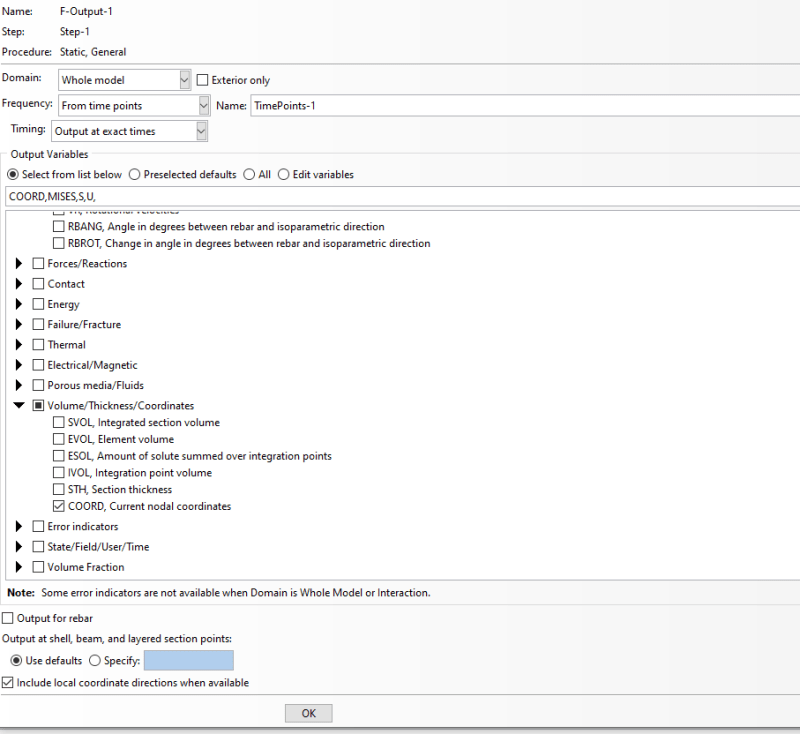
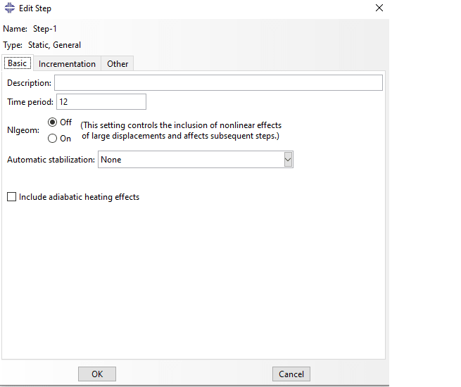
I am trying to perform a multi-step static analysis on shell elements by means of the subroutine DLOAD.

I extracted the stress history at a specific location (see attached illustration).
I do not understand the shape of the signal. When I look at the results, I can see that several values are reported at each time step, hence the unrealistic spikes one can see on the attached figure.

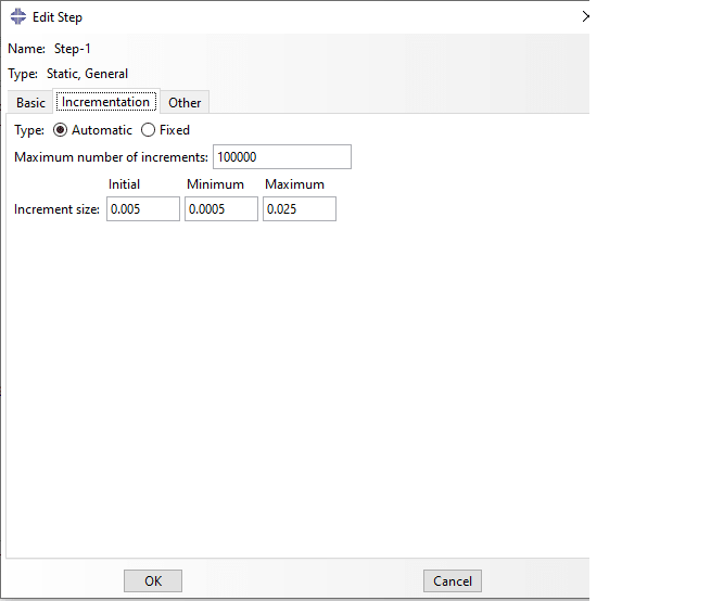
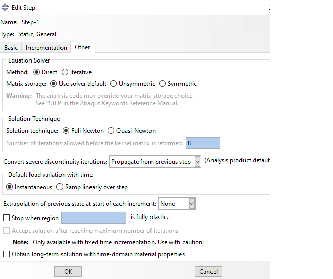
How can I solve this? I tried different in the solver under Steps but nothing works so far.

Thanking you in advance :)

Regards,
 
 https://files.engineering.com/getfile.aspx?folder=faadc910-5b3a-4feb-bbfd-0f316ec85494&file=stressHistory.png
Replies continue below

Recommended for you

Hard to say without knowing more about your analysis. How did you obtain this output ? What are the settings in the related output request ?
 
Hi,

The field output is defined as "from time points" where the timepoints are defined separately

The output is obtained at a specific node. I see the same trend for other variables such as displacement

FieldOutput_ob1bq8.png
step1_hilwpr.png
step2_rt3u3p.png
step3_xmtw8o.png
 
So you used the XY Data from ODB Field Output option to create that plot ? Why not request history output for that node instead (and set the frequency to 1 for more accuracy) ?
 
thank you for your reply :)

I need to export the results for an entire field of nodes. I typically export the results in a .rpt file.

It appears that at a given time step, several values are given, thus creating non continuous output signals.

I have to refine the meshing to capture as accurately as possible the moving load I try to simulate. It seems to help without solving the issue. The shell elements are of type S4.

Is there anything else I can do to guarantee a continous output ?
 
Hi,

I believe I have solved my problem by further refining the mesh and ensuring compatibility between the different shell elements (I use the submodelling capacities of Abaqus)
 
Status
Not open for further replies.
Back
Top