Continue to Site

Eng-Tips is the largest engineering community on the Internet

Intelligent Work Forums for Engineering Professionals

  • Congratulations waross on being selected by the Eng-Tips community for having the most helpful posts in the forums last week. Way to Go!

Overcharged Protected Li-Ion?

Status
Not open for further replies.

johnyradio

Electrical
Dec 30, 2013
15
Ok, i know you guys are going to laugh at me for even attmpting to do this, but here goes:

i purchased this battery. from a us-based vendor.


i checked the battery voltages on delivery. All were about 3.7 volts. Good sign.

i peeled away the base of one of the batteries, and indeed there was a little circuit board, with a conductor running up the side of the battery to the top.

i connected FOUR of these batteries in series. They gave 15.7 volts.

then i connected a 19 volt wall wart to the ends. after 15 minutes the batteries were warm, not hot. i disconnected, and the pack gave over 17 volts! That's too high-- a 4-pack should max at 16.8 V.

i checked each battery-- 3 batteries were under 4.2 V, but one battery measured 4.9 volts!

How could a protected battery charge to 4.9 V?

thx
 
Replies continue below

Recommended for you

I think you will find each battery has more than TWO terminals; the 'protection' gidgets use those other terminals to tell the device charging the batteries their condition via one of many possible schemes.

So seems to me you simply put the batteries themselves across the 17v wall wart and ignored the circuit board's smarts.

And without proper equalizing circuits around each cell, you cannot really charge Lion batts in series and get away with it many times - or that happens.

 
Guess I should have looked at the ebay site first; I don't see ANY connections so not sure how many connection points there are at all. I still cannot imagine a series FET or anything to stop charge/discharge but maybe and that one batt's FET is shorted?

 
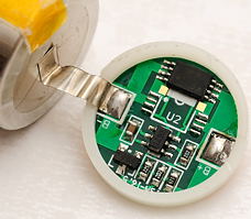
this is how they are assembled:

DSC_6242.jpg


ProtectedBattery.png
 
Never seen these things before, but based on what you've described, here's a possible scenario:

1. Batteries were good. The positive terminal is connected directly to the positive of the cell, and (via the thin wire) to the protection circuit (call it PC). The negative terminal is connected to the PC. If the PC thinks things are good, it closes a switch between the negative terminal and the negative of the cell.
2. 4 batteries in series, PC is happy, looks just like 4 cells in series.
3. 19Vdc applied, cells begin charging, and by good fortune they all reach 4.2V at about the same time.
4. Voltage on cell A reaches the upper threshold and the PC opens the switch.
5. Current from voltage source falls to zero immediately, and cheap wall wart puts out a spike.
6. 20V appears across cell A, switch fuses closed and PC dies.
7. Maybe other cells disconnect successfully, but eventually 19-(3*4.2) = 6.4V appears across one cell and it over charges.

All depends on exactly how the PC works, but as mikekilroy suggests charging cells in series with uncontrolled voltage sources is problematic.
 
ha, the vendor just gave me a full refund, when i asked why it charged past 4.2 v. He said "occasional bad battery!". what the....?

i found this "false plates without any protection function". They are identical to the plates on the bottoms of these batteries.

Question, can that 4.9V cell explode on the shelf, cool?
 
Question, can that 4.9V cell explode on the shelf, cool?


of course anything is possible, but no, it should not. lion batt or any other for that matter, happen when they get hot while overcharging (or in case of lead acid when a cell shorts).

if no current is flowing into or out of that cell, how is it going to get hot? It is not. I would expect it to drop in a week to normal level by self discharge (and that little pcb load).

Did you check the FET to see if it is shorted as suggested? If so, digikey and others sell replacements for a few cents; if you fix it and insist on series charging, why not buy 4 6v zeners to put across each also? But do realize that you will NEVER ever fully and properly charge all 4 cells in series - only ONE max....

 
there's no fet or diode, only the chip, but as i explained above, the chip is fake. there is no load.
 
OK so you got me interested enough to look at your documentation..... interesting.... You still need to do some basic investigating with an ohmmeter Johny...

The pcb 'fake' China list is ONLY fake on top chip of a 3 chip pcb shown - fake since it simply ties B- & p- together; other two chip spots do not have the shorting run under them.

You have single and double series FET sw (8205 - see so no clue if YOUR has the shorting runs under them or not from your pictures.

I do not think you wrote the "anatomy of a protec..." article as it shows different model pcbs and since all 4 of your batts are identical I really doubt you have different pcbs; so no idea which pcb you really have. I would not necessarily jump to the conclusion YOURs are fake....


Ohm across YOURs and see if the overcharge one isn't shorted (0 ohms) while the others are open with a batt lead off.

Removed the series FET and look under it if you want.

The pcb is simple enough you can draw the schematic if you want and see how it is supposed to work; I cannot see the controller chip IC no well enough to look it up from the pix shown or I might have drawn it for you.....

Very interesting non-the-less.


sorry, i don't follow you. This battery has a dummy pcb, just as shown in the links above. There are no fets. What do you mean?

what's a shorting run? there are no components on these pcb's, just blanks.

i did not say i wrote that article. i'm guessing english is not your first language?

thx anyway.
 
Keep in mind that even with a common language some ambiguity can remain. Your description style is particularly confusing. You've posted pics and links to describe your situation, and are now saying that they don't describe your situation. It's a bit hard to follow, so Mike's confusion is understandable.

johnyradio said:
there's no fet or diode, only the chip, but as i explained above, the chip is fake. there is no load.

Only the chip? Both FETs and diodes can be a chip. Do you mean the PCB is a fake? What makes you think it is a fake? You say it looks like the fakes, but isn't that what fakes are supposed to do - look like the real thing? In order to be a fake, there has to be no components soldered onto the pads on the PCB, and the negative of the cell has to be shorted through to the negative terminal of the battery. Why you'd both printing a PCB for a fake anyway is beyond me.

johnyradio said:
there are no components on these pcb's, just blanks.

Okay, new information, different from earlier. So you've cut one open and had a look? We're trying to follow, honestly we are, but all we have to go on is what you have provided so far. Even without the components, there has to be some connection to the negative terminal. The fakes are pretty elaborate for that purpose. I'm now plenty confused, and English is my only language!
 
how do you cut open a pcb?

as i said, the pcb's on these batteries are identical to the pcb's in the listing of fake pcb's. Look at the photo. There are no components on the pcb.

yes, i don't know why these chinese producers bother, when it seems it would be about the same cost and effort to use real pcb's. But they are famous for selling fake li-ion batteries on ebay, so why not with fake pcb's?
 
Liteyear, do you want to try to answer how to 'cut open a pcb' or should I? Cute.

I still have no clue if your pcb has parts on it as you showed originally or not. And if not, why did you even ask a question about it?

JohnyMeBoy, methinks your whole posting here is to make some kind of political statement about "those darn Chinese;" you need to go to utube for that, not here.

 
no, i'm not here to politicize, i'm here to get technical answers to technical questions.

The photo of the pcb with parts, in case you did not bother to visit the link i provided, is a generic photo from the link i provided, showing how round pcb's are connected to protected cells. I provided that to inform the poster who said he'd never heard of that kind of pcb on a cell. That is NOT a photo of my own pcb's, sorry if i did not clarify.

The photo of MY pcb is at the link i provided with the verbiage, "They are identical to the plates on the bottoms of these batteries."

still waiting for the answer to "how to cut open a pcb".
 
LOL, I meant cut open the battery to look at the PCB. Anyway, I'm pulling the ripcord. I sense the ground is rushing up fast to smack us all the face. Enjoy the rest of the ride!
 
I might be wrong, but i don't think they ever put the pcb inside the batteries. Just chemicals :)

Anyway, today i had success charging and recharging these batteries, with an EXTERNAL charger. They appear to work as li-ions, without any explosions (even tho their protection pcb's are phony).

Thanks everybody for your comments!
 
Status
Not open for further replies.

Part and Inventory Search

Sponsor