Hello,
We have a heater whose resistance increases substantially as it heats up, meaning its current draw decreases. If left on too long at full power (~8-12 s) it can get too hot and cause issues. Normally the heater is used in a PID loop to prevent this, but that cannot be counted on without more robust safety measures (functional safety is not feasible at this time). So I need to find a fuse, breaker, or some sort of passive device(s) that can interrupt the heating circuit if the heater stays on too long. I have looked at many time delay fuses and some circuit breakers but none have had the needed I vs. t characteristics.
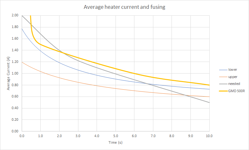
The chart below illustrates this: the blue and orange lines represent the average current vs. time for the min and max heater resistance tolerance (so the value shown at e.g. 1 s is the average of the current drawn from 0-1 s, the value at 2 s is the average from 0-2 s, etc.); the grey line is roughly what I need; and the thick yellow line is the best matching fuse I have yet found.
As you can see, the fuse stays above the blue and orange lines the whole time, meaning it will never blow.
For the grey line, which again approximates the I vs. t characteristics I need, the only important feature is that it is above both the blue and orange lines for at least the first 5s or so, and below both of those within about 10s. So it can be slightly above/below or drastically so, as long as it crosses somewhere in the 5-10s time-frame. (The portion from about 0.5-2 s where the fuse line dips below this line is ok since its still above the min/max current lines.)
Do you know of any passive devices or circuits that can accomplish this?
BTW the other option we have identified is to put a thermal cutoff switch near the heater, but this is a difficult challenge in this application.
Thanks!

