Eng-Tips is the largest engineering community on the Internet

Intelligent Work Forums for Engineering Professionals

Overhanging/Cantilever Car Port

Status
Not open for further replies.

TORCHMAN

Structural
Sep 8, 2023
68
0
6
CA
Good Evening Engineers,

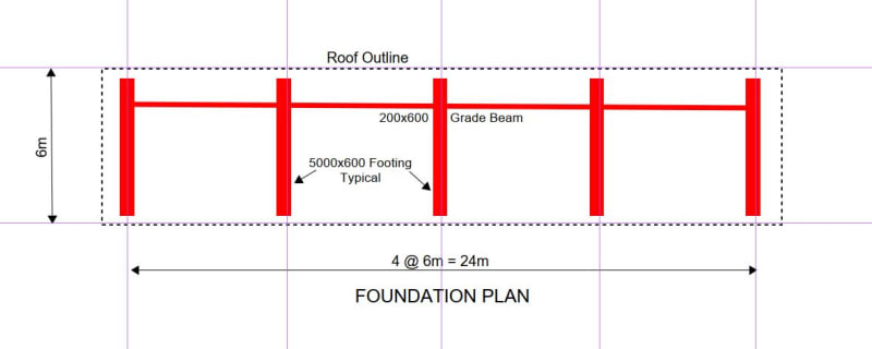
I am designing a commercial carport with supports only at the back. Below is a picture of roughly what I am trying to achieve. The location has a relatively low snow load of 1.2kPa but it poses a challenge! I have tried modelling a couple of options and I am wondering what you guys think. What is interesting is my designs are based on a post at every stall (10') while the picture below shows one at every 3 stalls! Maybe that area has no snow. Loads shown are SLS.

Question1: What is an acceptable deflection for something like this? Since no finishes on the underside, I wonder if L/240 would be acceptable.
Question2: This is a 2D design, I wonder if once the diaphragm goes in or if I X-brace them together, they will perform better?

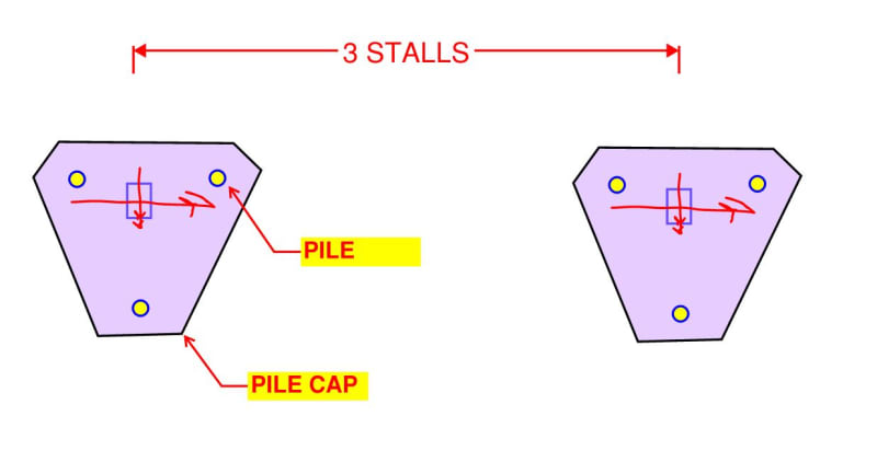
The first option is great but leads to a large uplift on the back column which I'll have to check if I can resist by pouring one footing for both piers

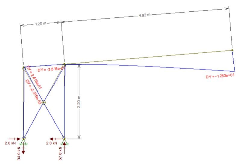
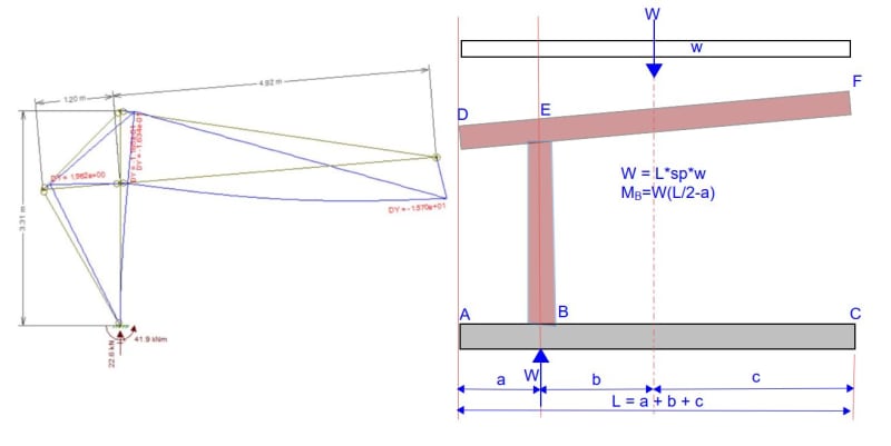
The second option I think looks cooler but I have found so far that the moment connection at base would be quite large. I placed the post 4' in from the back to decrease the moment but the moment is still so large that it would require sizeable footing that would not fit in between cars. Modelling the carport as shown in the picture yields a ridiculous moment at base.
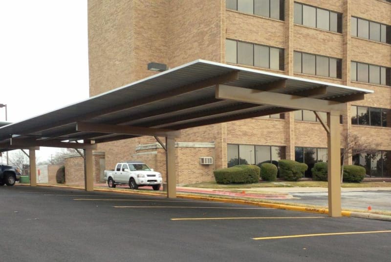
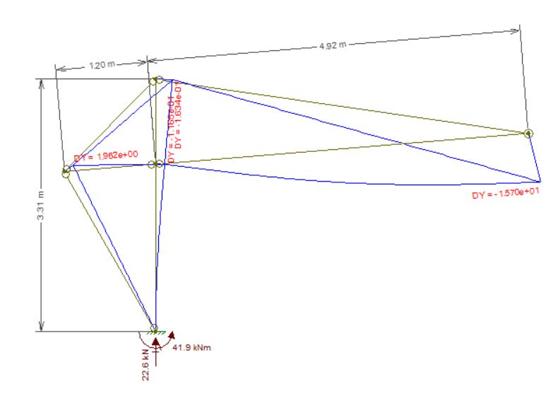
Cantilever_Carport_tc4tox.jpg

Carport_Model_B_dgksw4.jpg

Carport_Model_A_gdmeiq.jpg
 
Replies continue below

Recommended for you

It is not that bad. I would use a steel beam section, braced at the quarter points. The footing ABC is centered under the center of load. Moments in the steel are quite manageable.

If L is considered to be 5000, L/240 = 21mm. That should be acceptable.

Capture_eskakg.jpg
 
and a horizontal beam at the column line to accommodate any lateral loads at right angles.

-----*****-----
So strange to see the singularity approaching while the entire planet is rapidly turning into a hellscape. -John Coates

-Dik
 
BAretired said:
The footing ABC is centered under the center of load.

That would be quite the footing! Imagine for every stall making a 20' long footing. I believe the single support cantilever carport idea is not economically sensible in an area with a 1.2 kPa snow load.

Maybe with the double support, I will work on designing a smaller pad footing to see if it is feasible.

dik said:
and a horizontal beam at the column line to accommodate any lateral loads at right angles.
Sorry, not sure if I understand. Is it best to keep the beam on the horizontal rather than on an angle?
 
I think what dik is suggesting is make a moment frame in the longitudinal direction. To reduce the footing size could you use helical piles with a pile cap or something of the sort? You could batter them for increased lateral in all directions as well (though sticksandtriangles will come and tell us how that is maybe not the greatest [bigsmile])
 
Torchman said:
I placed the post 4' in from the back to decrease the moment but the moment is still so large that it would require sizeable footing that would not fit in between cars.

That does not make sense to me. I can't imagine you cannot fit a footing in here.
I would be designing this in 2D (because that is all I have :)). I can't imagine you will gain anything as a 3D model.
 
It's a nice carport, but appears to be a little 'wobbly' in the longitudinal direction. I don't know what load it's subject to.


-----*****-----
So strange to see the singularity approaching while the entire planet is rapidly turning into a hellscape. -John Coates

-Dik
 
torchman [COLOR=blue said:
and BA[/color]]That would be quite the footing! Imagine for every stall making a 20' long footing. I believe the single support cantilever carport idea is not economically sensible in an area with a 1.2 kPa snow load.
I was thinking of a footing, column and beam every third stall, which would be 30' o/c, but every second stall, i.e. 20' o/c is perhaps a better option. If the length of the footing bothers you, point A and C could each move closer to B and still keep the footing centered under the load. The width would increase, but the area would remain the same. The most economical footing is centered under the load. The scheme is perfectly sensible for a 1.2 kPa snow load.

Maybe with the double support, I will work on designing a smaller pad footing to see if it is feasible.
You can work as hard as you like, but you cannot design a smaller footing than one which is centered under the load.


Well, consider a square, rectangular or circular footing under a centrally placed column such that maximum allowable soil pressure exists over the entire area. If the column is moved horizontally, even a little, bearing stress must increase somewhere.
 
I think you also need to investigate the potential for wind deflections going ballistic on you (think Tacoma Narrows Bridge).
The flexibility of a carport can be susceptible to galloping and flutter, etc. (not sure I'm using these terms correctly with respect to the upward-downward oscillation of the roof under wind).

I'd be wary of relaxing deflections because of this.

There is an AASHTO document (Structural Supports for Highway Signs, Luminaires and Traffic Signals) has some info on this wind effect. Not sure if you can apply it to this kind of roof.


With a large moment (at the base of the column) that may not be the case. I can see the footing extending in the direction of the cantilever.

-----*****-----
So strange to see the singularity approaching while the entire planet is rapidly turning into a hellscape. -John Coates

-Dik
 
Enable said:
You could batter them for increased lateral in all directions as well (though sticksandtriangles will come and tell us how that is maybe not the greatest bigsmile)

Hey, I'm fine with battered piles as long as the person designing them acknowledges there's a little more to it than "these are here for lateral resistance" [infinity]

S&T
 
I like the three stall arrangement:

1) It allows you do concentrate foundation resistance efficiently.

2) It echoes traditional structure column spacing where parking is concerned, thus improving the odds that it meets typical expectations.

One foundation option is shown below. Obviously, it's nowhere near as economical as, say, a bunch of 5' square pad footings. But, then, the economy liner left port with the decision to sport the big, sexy cantilever.

c01_ckkxws.jpg
 
I haven't had time to read through all the posts here yet, but wanted to quickly throw out what I typically see, although I don't agree with it:
1. I see Risk Cat 1 all the time on these, I prefer II (probably one of the reasons I don't do a lot of these).
2. I see minimal live loading on the designs of these normally (their justification is no one should ever get on there for maintenance). Again, I don't agree with this.
3. Locally most of these have 0 snow loading.
4. Locally few engineers look at deflections of the system, and only look at individual members, using L/60 or 120/150 sim to PEMB's (I have even seen less).
5. I see engineers trying to say asphalt provides restraint at the caisson to reduce the depth, I disagree with this as it's not rigid as required per code.
6. I have also seen isolated pole factor applied to geotech loading while using restrained, also not allowed per code.

Based on this, I'm not surprised you have the results you have as you appear to be looking at this correctly.
 
Could use a three stall arrangement, but below is a suggested foundation plan for a two stall arrangement, using footings, not piles. Piles could be used if frost heave is a concern.

Capture_b8cyee.jpg
 
I would be looking at a drilled pier type foundation under each column if this is an existing parking lot, that would allow you to install without having to replace existing parking surface when it is removed to install spread foundations.
 
Status
Not open for further replies.
Back
Top