Continue to Site

Eng-Tips is the largest engineering community on the Internet

Intelligent Work Forums for Engineering Professionals

  • Congratulations SSS148 on being selected by the Eng-Tips community for having the most helpful posts in the forums last week. Way to Go!

overhead sign support angle top and bottom chord

Status
Not open for further replies.

delagina

Structural
Sep 18, 2010
1,008
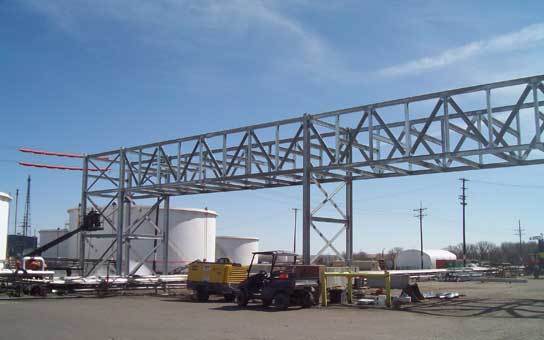
i design pipebridge (not an actual bridge see pic attached) from time to time and in all cases i had to use wide flange beam for bottom and top chord because of bending.

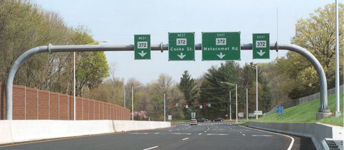
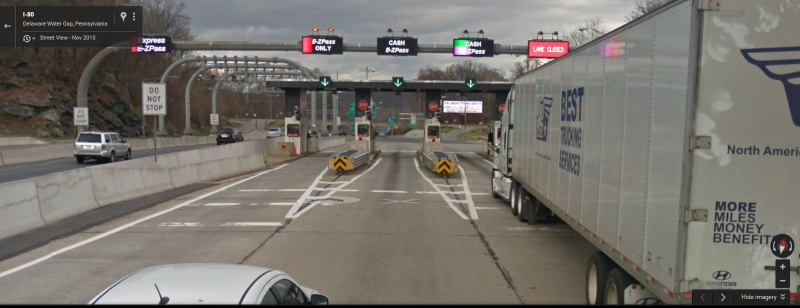
i'm confused because i see these sign supports all the time in freeway some even around 100' and angles are working fine.

can someone link me the analysis of these supports. are the bottom and top chord assumed as axial only because i cant see these angles passing if it were to take bending.


images_jdscbv.jpg
 
Replies continue below

Recommended for you

nevermind i should have googled first.. i see some pdf online re overhead sign support design.. i'll just compare it with how i design my top and bottom chord.. i usually analyze it as one long beam with shear connection at the ends..
 
The sign gantry in your photo has trusses both vertically and horizontally. So the members are not typically designed for bending. But that one does look skinny. I don't know how it works for loading transverse to the roadway.

I like your pipebridge much better.
 
NYSDOT has standard sign structure designs, based on sign area, span, and height Link. You can use these as a sanity check. I'm sure other DOT's have similar tables.

The only sign structures we design in NY are ones carrying VMS. They're quite heavy at times and the size of the sign is specific to the location. These are quad trusses, which we design as a space truss. The truss is simply supported. The members are always round sections. I attached the NYSDZOT sign structure design manual for reference. I'll also post the VMS design manual.
 
 http://files.engineering.com/getfile.aspx?folder=b18d0208-0343-41c4-b7ba-5543f5b64a1c&file=NYSDOT_Sign_Manual.pdf
FYI I didn't design the attached pipebridge pic. It was a pic I saw online. I have designed numerous pipebridge similar to that though and I ALWAyS have wide flange as bottom and top chord. Not sure how a 100' sign support pass with just angles as top and bottom chord.
 
I've never seen a long span (or for that matter a short span) sign structure with angles as top & bottom truss chords. Always tubes, round, rectangular, or square.
 
We re-purposed an old highway sign that was salvaged when a road was widened or something. It was re-used as traffic guidance for entering and leaving a driveway on a motor speedway. The span we used was about 70' after modifying the truss. I believe it was over 100' originally.

Anyway, the whole thing was built from angles. 6x6x1/2" for the (4) chords and 3x3x3/8" for the diagonals. It was 4'-5" wide and 5'-9" deep.

Link

 
So how do you analyze this using 3D software.
I model mine as one continuous beam for top and bottom chord, shear connected at the column. Vertical and horizontal brace as truss member.

Is there another way of analysis for this truss? Can this be analyze as one built up shape basically just one member?

I haven't read the PDF I downloaded. I'm curious how those angle top and bottom chord are passing.
 
I guess I don't understand why the sign guys stay away from angles. I just designed a long pipe rack and while I didn't use angles for the chords, I used WT's, which seem pretty similar.
 

My guess, in no particular order:

Aesthetics;
No horizontal projections to accumulate snow, debris or provide a home for pigeons;
More torsional rigidity with a tube versus angle;and
That's what the DOT tells us to use

From a fabrication standpoint gusset plates with angles is easier.
 
Look over ASCE 10 for some hints on how angles are used in Transmission towers. There are specialty software programs like PLS-CADD, but the design is mainly done as a 3D truss with some adjustments in the compression allowable for concentric connections and end restraint. My last big design was a free standing river crossing structure that was 332'-0 tall made from all angles to withstand a 120 mph hurricane. The unique aspect of our industry is that we do full scale testing of towers to destruction to see if we know what we are doing. You can afford to destroy one for proof of concept when you are going to build 1000 copies over the next 20 years. We even have our own ASTM A394 bolts to keep the threads out of the shear plane.

The telecom industry does use round solid or pipe type legs with welded gusset plates on their 3 sided free standing towers. They do sometimes use 60° angles as legs.

_____________________________________
I have been called "A storehouse of worthless information" many times.
 
I've used the pipe kinds for a low clearance warning. I "borrowed" a lot from our state DOT. I think the verticals were Schedule 160 12 inch pipe. I couldn't really justify them, structurally (they were under stressed), but I still used them and never looked back.
And it's still there to this day.
 
hokie,

I'll see your monotube and raise you 3 monotubes. This one's about 15 miles from my house. It was erected about 12 years ago and one of the first uses of a monotube sign structure in the region.

d_kepiop.png
 
The monotube supports are very popular here in Australia. Not sure I deserve it, but I take credit for introducing them to Queensland. In the design of a freeway project here, the authority involved an architect for some reason. Anyway, he came to us for advice on the overhead signage, and thought my suggestion of these looked clean. They do. That was about 25 years ago, and the rolled tube type are prevalent here now.
 
nobody still answered how angle chords should be modeled in 3d software. should it be modeled as continuous beam, shear connection at the ends?
 
Monotubes were manufactured by our company for federally funded interstate construction jobs in Ct.. The beauty about monotubes is that they were relatively easy to manufacture and paint. To bend the sections, a subcontract was invoked but we did the welding.
 
Status
Not open for further replies.

Part and Inventory Search

Sponsor