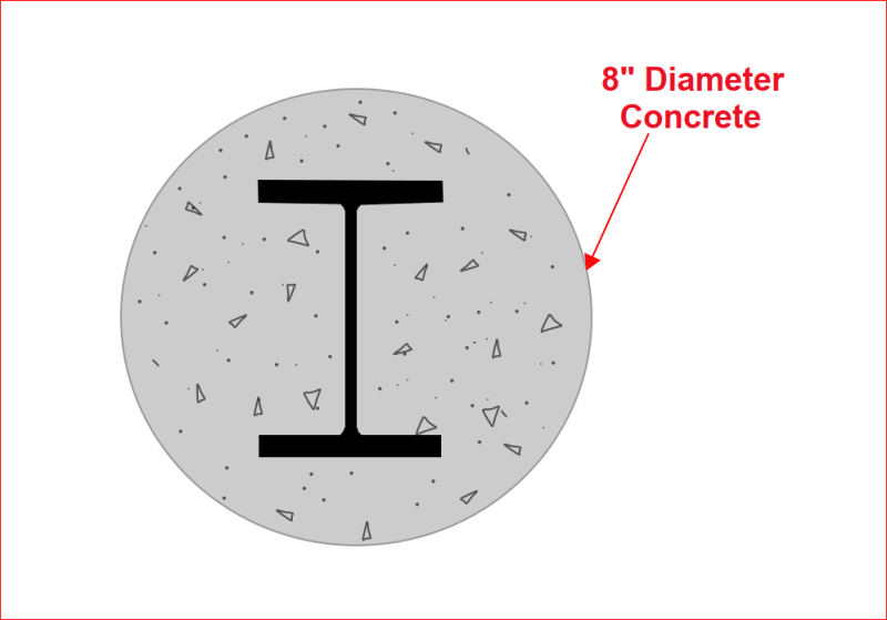
Is it possible to overlap members in RISA 3D to simulate a composite member? I'm trying to make a section where it's a wide flange enveloped by an 8" diameter round concrete. Originally, I had a built up section in RISA Sections but I realized that modulus would have to have been different for it to work.
Navigation
Install the app
How to install the app on iOS
Follow along with the video below to see how to install our site as a web app on your home screen.
Note: This feature may not be available in some browsers.
More options
Style variation
-
Congratulations TugboatEng on being selected by the Eng-Tips community for having the most helpful posts in the forums last week. Way to Go!
You are using an out of date browser. It may not display this or other websites correctly.
You should upgrade or use an alternative browser.
You should upgrade or use an alternative browser.
Overlapping members in RISA 3D 1
- Thread starter fzlo
- Start date
- Status
- Not open for further replies.
JoshPlumSE
Structural
Honestly, it could work. If you use "physical" members, they will automatically connect to any nodes that occur along their length. So, two members that occupy the same space would connect to each other at each node along their lengths.
That being said, you have to be careful, because any "model merge" would tend to get rid of one of those members. If you want to avoid this, you could have another member defined somewhere completely off in space, then use "nodal slaving" to constrain this member to the other member at various locations.
You should be able to run a couple of simple test models to confirm that it's working the way you want it to.
-
1
- #6
JoshPlumSE
Structural
fzlo said:Is it possible to overlap members in RISA 3D to simulate a composite member? I'm trying to make a section where it's a wide flange enveloped by an 8" diameter round concrete. Originally, I had a built up section in RISA Sections but I realized that modulus would have to have been different for it to work.
I should also point out that this could be done in RISASection as well. If I remember correctly, each shape in RISASection has a 'property' multiplier that is meant to be the ratio of the E value for that material vs the standard material used to define the overall section. There should be example problems of composite members that are installed with the program.
Caveat: I used to work for RISA. I now work for one of their competitors. So, I am not a neutral observer when it comes to RISA. Though my criticism of them is usually related to ownership / management and its treatment of customers or employees.
Composite members normally require welded shear studs to transfer shear stress between concrete and steel. An eight inch diameter concrete cylinder doesn't leave much room for a steel beam. The concrete should have nominal longitudinal bars and circular ties around the steel beam to prevent concrete from separating from the steel.
A W4x4 is the largest beam which could be used. Doesn't sound very practical.
BA
A W4x4 is the largest beam which could be used. Doesn't sound very practical.
BA
It's been several years, but I was curious about something similar once. I did a hand calc to figure out how I expected the member to behave, and then modeled the members of a built up section in RISA using offsets and then tied them together with rigid links at 12" on center to simulate welds. I think it was in the ballpark, so I was happy enough with it to run a preliminary model but it wasn't accurate enough to use for final design. The firm I was working for at the time didn't have RISAsection.
JoshPlumSE
Structural
phamENG -
Hmmm, I'd have to see the model to make a better guess. But, my thoughts (without knowing more) are the following:
a) Your basic premise is sound. Rigid links connecting a steel beam to a concrete slab is a reasonable way to model a composite beam.
b) You have to be careful about the end conditions. You don't want to create moment resistance at the ends. That's the real tricky part.
c) What you describe is probably close to "full composite" action as opposed to partial composite action. I'm not sure there is a good way to use RISA to get partial composite action.
BARetired has a good point, either method of modeling this member assumes that there is sufficient ability to transfer shear between sections. My tendency is to think this is more important for composite BEAMS than it is for columns. Most of my experience in composite members has been with beams rather than columns. So, if there are intricacies related to getting composite action with columns, I will leave that to others more experienced on the subject.
I made a pham-type model once. It was to settle a debate with some coworkers about reinforcing a glulam with LVLs. This has been hashed out multiple times here as well.
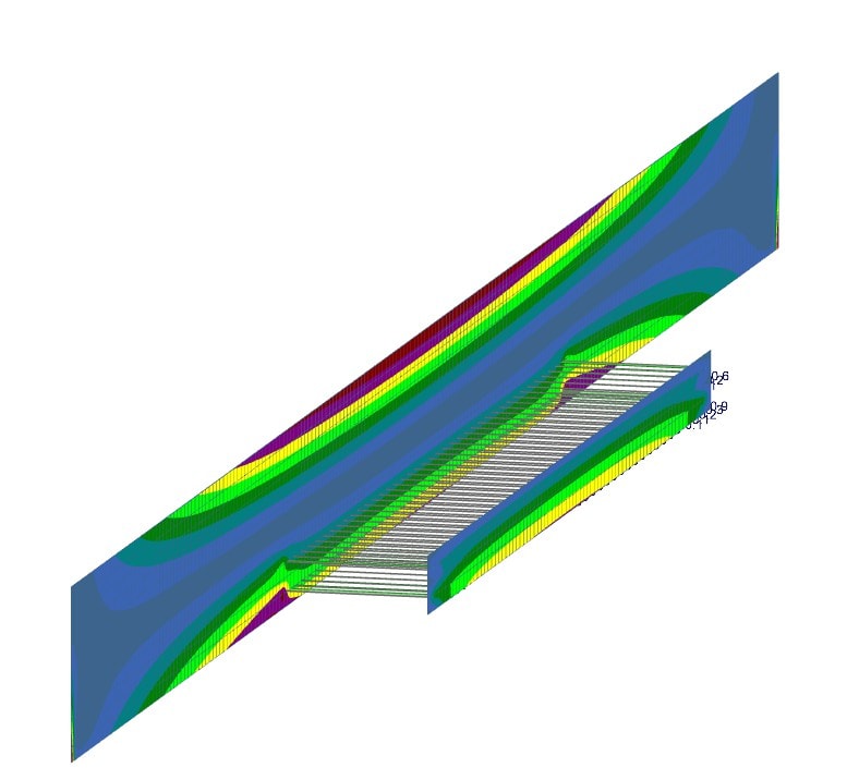
Glulam and LVLs modeled as plates of respective thickness and material and meshed to 3". 6.75x34 glulam and 2 12" LVLs. Uniform load full length. I added rigid links for the screws and pinned/torque releas-ed them to get it to behave. Don't mind the ridiculous offset, that's just so you can see the results. Contours shown are mises stresses. IIRC the argument was about how quickly the fasteners picked up the load. I turned on member shear diagrams. You can see it dumps almost all of the load into the first few columns of fasteners which seems pretty intuitive.
Kinda sorta related to OP's question. I'm interested to see what Josh's take is.

- Thread starter
- #11
BAretired, Yes, the drawing you showed is what the Port had installed. They used a W5x19 as a micropile and our senior engineer agreed that it wasn't providing much support which is why we were trying to see how much it can actually hold.
JoshPlumSE, when I built the section in RISA sections, I realized that I would have needed to change the modulus to be a composite as well but I was unsure how to to do it. The member wouldn't really have the modulus of just the concrete or the steel since it was a mix of both.
JoshPlumSE, when I built the section in RISA sections, I realized that I would have needed to change the modulus to be a composite as well but I was unsure how to to do it. The member wouldn't really have the modulus of just the concrete or the steel since it was a mix of both.
Without the ability to define the how the steel interacts with the concrete this will be difficult to do with any confidence. If you have connectors like BA suggests, then your results could be reasonable since your model will be suggesting a perfect bond between the two.
JoshPlumSE
Structural
fzlo said:JoshPlumSE, when I built the section in RISA sections, I realized that I would have needed to change the modulus to be a composite as well but I was unsure how to to do it. The member wouldn't really have the modulus of just the concrete or the steel since it was a mix of both.
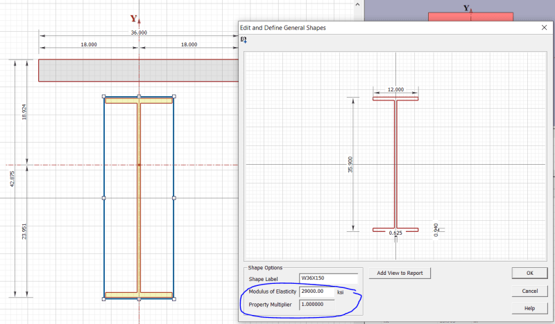
Just to show you how this would be done in RISASection, when you double click a shape, it brings up the properties for that shape. See the images below from RISA's example problem for composite beams. Notice how each shape has a "modulus" of elasticity associated with it?
Since the property multiplier is 1.0 for the steel beam, you know that the "base modulus" is steel's 29,000 ksi


- Thread starter
- #14
- Status
- Not open for further replies.
Similar threads
- Locked
- Question
- Replies
- 5
- Views
- 3K
- Locked
- Question
- Replies
- 10
- Views
- 2K
- Locked
- Question
- Replies
- 1
- Views
- 785
- Replies
- 5
- Views
- 6K
- Locked
- Question
- Replies
- 10
- Views
- 1K

