Continue to Site

Eng-Tips is the largest engineering community on the Internet

Intelligent Work Forums for Engineering Professionals

  • Congratulations KootK on being selected by the Eng-Tips community for having the most helpful posts in the forums last week. Way to Go!

overshoot nonlinearity

BOBO0215

Student
Dec 18, 2024
2
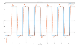
I am controlling the DC motor in school as a project. But when we analysis using simulink, we shouldve got overshoot in both side. However we only got overshoot at the increase pulse. Im not able to adjust K_p and K_I to reduce the overshoot, what I want is the reason or the resource that describe this to put in my analysis. Does anyone know?
 
Replies continue below

Recommended for you

1734535713358.png
 

Attachments

  • KakaoTalk_20241216_213725454.jpg
    KakaoTalk_20241216_213725454.jpg
    1.5 MB · Views: 6
What exactly is the "response" plotted on the y-axis? Input current to the motor? Motor rpm? What device is used to measure that (transducer?). What does the model measure? Can you show a schematic of the wiring and the mechanical setup?
 
your scope appears to be showing inductive kickback voltage spike when the current is suddenly interrupted. Conversely when the current is applied the voltage rise will be delayed, as your scope trace shows.
 
That first graph s the simulink output, the far more interesting 2nd photo is the test result. Are these speed? My guess is that your Simulink model of the motor is not sufficiently accurate, rather than the PID side of things. what sort of motor is it, what is the load on it?
 
Your scope photo shows unsymmetrical slew rates for rising and falling edges; specifically, the falling edge is slew-rate limited, i.e., something in your driver is limiting the fall rate so severely, that it's not enough to generate an overshoot.
 
I agree with Greg, it sounds and looks like you are modelling motor speed (rpm), given the rounded overshoot (vs. the spike of an inductive kickback). Why no undershoot - probably because you are not modelling friction (both coulomb and viscous) in the motor bearings, and/or have a model that over-estimates the rotor inertia, and/or have a model that puts negative voltage on the motor wires when the motor is commanded off (versus voltage just going to zero in the real case).
 

Part and Inventory Search

Sponsor