Eng-Tips is the largest engineering community on the Internet

Intelligent Work Forums for Engineering Professionals

Overturning bearing pressure with uplift present 2

Status
Not open for further replies.

YoungGunner

Structural
Sep 8, 2020
98
0
0
US
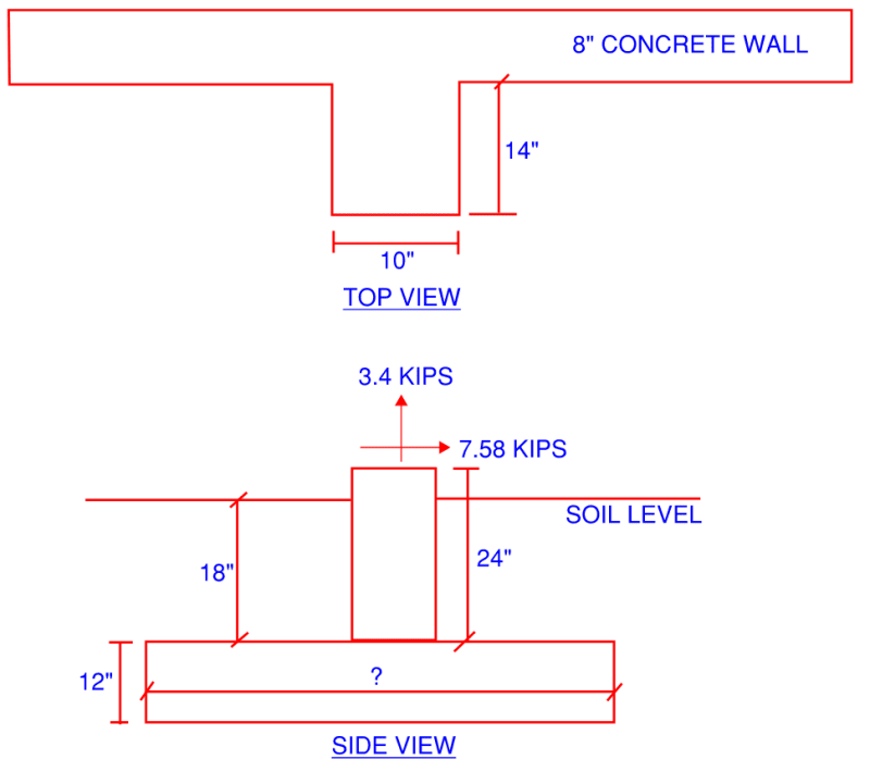
Got the following situation for a metal building foundation pier and I'm struggling with the idea of having uplift when solving for soil bearing pressure. The forces shown are ASD and are from a seismic load combo. As you see, there is net uplift and a lateral bracing force at the top of the column. The uplift absolutely wrecks the eccentricity of the M/P unless footing size is increased significantly to add weight above to counteract the uplift. This is a relatively tiny building (30'x48') and so far a 48"x48" wide spread footing has been sufficient for every other load condition, but for this one load case I would have to increase the footing to around 70"x70". This large a footing would be ridiculous to any builder for this size of metal building and I'm worried other engineers know tricks I'm unaware of.

Looking for some tips and tricks on how to reduce the eccentricity other than merely increasing the overburden weight, or if there is any justification for not checking bearing pressure for a load combination that has net uplift. Is there anything to be said for we can't have bearing pressure pushing down if I'm just trying to keep the footing from lifting up?

Capture_wsl1p8.png
 
Replies continue below

Recommended for you

Are you sure you aren't incorrectly combining load combinations?

Seismic doesn't often dominate* in overturning scenarios as it increase linearly with mass which in turns reduces uplift. *(except, I expect, slender building in high seismic zones). This is even more likely to be the case for lightweight steel buildings.

I deal with lightweight slender steel structures that are very much influenced by overturning, but wind is dominate in overturning by a long way. (despite the seismic loads being significantly higher)

If you are combining the ultimate seismic load calculated with one mass case with a stabilising load from another mass case then you can readily end up with seismic dominating. I've seen it done before and had to politely correct our external foundation consultants.

 
Doesn't your concrete wall - integral with the pedestal and footing, simply take the lateral shear out of the footing? We usually assume it does.


The check should include the self weight of the foundation shouldn't it? If there's net uplift (including the self-weight of the foundation), isn't that an automatic failure seperate to the bearing check that requires increasing the weight of the foundation anyway?

Assuming US from the kips so can't comment on codes.
 
Appreciate the responses so far. Few things to unpack.
1. This metal building appears to be torsionally braced, so for this load case, one x-brace is taking the entire base shear in one direction. The dead weight from the building is so low it isn't counteracting the uplift which results in a starting uplift at the top of the pier. This is the simple load combo of 0.6D + 0.7E. I'm not combining values from different load combos.
2. I like JAE thought and it's one I hadn't considered. I was doing a method of combining the wall footing as an extension of my main spot footing which helped, but wasn't enough. I guess you're saying that there isn't a moment applied to the footing of the pier can't rotate and it can't rotate because it's connected to the wall? Maybe up to a certain loading but I don't know how to check at what point a twisting pier will separate from the wall. Shear is part of it but rotation is there too.
3.To clarify, the loads shown above are the loads applied to the top of the pier. Those values have not yet included self weight of the foundation itself. Uplift itself is resolved through the mass of everything around, but because the uplift starts so high, and to determine eccentricity of the footing is e=M/P, having a small P (downward force) results in a high eccentricity which destroys bearing pressure in the following calcs. I realize this will be the case for any load case with a smallish vertical load and the only way is to massively increase the footing to increase P and reduce e, but wondering if there are alternatives to this thought. JAE had a good thought, I just don't know how to quantify that.
 
You bring up a good point about the twisting pier. There is a net eccentricity of the shear force that needs to be considered when transferring load from the pier to the connected wall.
My approach would be to first transfer the shear from the pier to the wall via shear friction (design enough reinforcement to bite into the wall to transfer this shear).
After this, there will still be a net "twist" that needs to be resolved. I believe adequate ties intersecting the concrete breakout plane of the shear transfer mechanism (shear lug or anchor rods, whichever one you use) to develop and resist the tension generated due to the eccentricity of shear need to be designed in addition to the shear friction component. That way you are designing for the shear and the induced eccentricity along the load path.
 
 https://files.engineering.com/getfile.aspx?folder=4242a1c8-bcf1-4f42-9ccf-6aa5d7aa395d&file=shear_transfer_sketch.pdf
What is your allowable bearing? With the numbers you show I get about 2500 psf with a 6'x6' footing (Excluding any weight from the concrete wall).

Since allowable bearing pressure is often controlled by long term settlement, geotechnical engineers will sometimes allow you to increase your allowable bearing pressure by 1/3rd when checking load combinations that include transient loads like wind and seismic. I've even seen some say it can be increased by up to 50%. If you aren't doing this already, you may check your report/ask your geotech about this if you're having bearing trouble. This is usually my first "trick" when I have bearing trouble with lateral load cases.

If your footing plan dimensions are getting bigger than you like, you may also think about making it thicker. Adding thickness is not as effective as adding length when it comes to reducing bearing pressure, but it can help to reduce the eccentricity. As it gets larger, you may have to increase thickness anyway due to shear checks, especially if you're under ACI 318-19 here.

Also, just my opinion, if there are only two footings carrying the entire lateral load in that direction in a seismic region with poor soil, the builder should except those footings to be quite a bit larger than the typical ones.
 
Agree with andrews2 in spirit about increasing allowable bearing pressure for transient loads. But the actual way to do it is to reduce the overturning load, not increase the allowable bearing pressure. Unless I'm misinterpreting it myself, I think this is code that has been misinterpreted for a long time. Code snippet from ASCE 7-16:

Screenshot_2024-04-20_134942_hcr0ht.png


Reducing the overturning load has less of an effect than increasing the allowable bearing pressure. I usually take care of this by adding some load combinations where W or E is multiplied by 0.75, just for bearing pressure check.
 
I believe any time I've used the reduction from 12.13.4 it's been for general stability in an overturning spread footing, not for bearing. Although, I suppose with the wording being "Overturning effects" you can probably justify this as reducing bearing pressure as well.

The increase in allowable bearing pressure that I have used is not something I get from any code, it is given to me by the geotechnical engineer. With allowable bearing pressure so often controlled by long-term settlement, I trust their judgement in allowing an increase for transient loads. Sometimes they do not allow the stress increase. Every project and geotechnical engineer is different.

Just to be clear, I would not increase allowable bearing according to the geotech and decrease the applied bearing in accordance with 12.13.4. They are technically different sources, but I think their intent is the same, so I would only do one of the two.
 
In situations similar to this, I have often ignored the load combos with 0.6D in them when calculating soil bearing pressures and will instead substitute a combo using 0.9D and ensure that I have an overturning safety factor of at least 1.5 in that combination. Same effect, but doesn't unnecessarily crush the soil bearing calculations with high overturning and low axial loads or uplift.

I'd be a little more cautious in your case with global stability WRT uplift & overturning b/c you're bringing in uplift from a braced frame. I'm usually dealing with a single cantilevered column using mass of the foundation to resist OT.

I'm sure we've discussed this here before, but IMO this is an unintended consequence in the 0.6D load combinations which were added when the 1.5 FOS was removed from the code.
 
The reduction in overturning effects allowed by ASCE 12.13.4 is an acknowledgement that ELF produces conservative overturning forces since 100% of the building mass is assumed to participate in the first mode. MRSA is not as conservative with respect to overturning, hence the lower reduction allowed. Since these reductions are rooted in mass participation, it isn't really appropriate to apply them to single story structures like the one in the OP.

The increase in allowable soil bearing pressure is for short-term loading as andrews2 described. So the reduction in overturning can coexist with the allowable soil bearing increase since they are each accounting for separate effects.

Not sure I agree azcats' approach since it doesn't explicitly check that soil bearing pressure is adequate under the code required load combinations, and as far as I can tell the safety factor approach is only permitted for retaining walls (IBC 1807.2.3). That said, for situations where seismic uplift / overturning is driving the design, you can use a load combination of 0.9D + E/1.4 from the Alternative ASD Load Combinations of IBC 1605.2, and this doesn't require checking for an additional safety factor. This load combo is not permitted to be used with the overturning reduction from ASCE 12.13.4, but can be used with the allowable soil bearing increase for short-term loading if appropriate.
 
I'm a tad confused by this setup but a few thoughts to add
1) If you just ignore the column eccentricity from the wall (for now) does it calc out?
Are you allowing that eccentricity to confuse you?

2) Your footing seems to be a decent depth below ground
Can you put in a bunch of steel to the footing then utilise soil to resist the uplift loads?

3) Is that concrete wall continuous the whole way down the building?
If so, surely there's a way you can incorporate that/the strip footing underneath it to improve your design
 
I found this thread regarding 12.13.4 and it does mention overturning and strength design, but not bearing pressure. I personally think these reduced forces can be applied to bearing pressure, because that follows from overturning, but not in combination with an increased bearing pressure given by a geotechnical engineer.

Just to copy the NEHRP, in support of what deker was saying:

2009 NEHRP provisions:
C12.13.4 Reduction of Foundation Overturning. Since the vertical distribution of forces prescribed for use with the
equivalent lateral force procedure is intended to envelope story shears, overturning moments are exaggerated. (See
Section C12.13.3.) Such moments will be lower where multiple modes respond, so a 25 percent reduction is permitted for
design (strength and stability) of the foundation using this procedure. This reduction is not permitted for inverted pendulum
or cantilevered column type structures, which typically have a single mode of response.
Since the modal response spectrum analysis procedure more accurately reflects the actual distribution of shears and
overturning moments, the permitted reduction is only 10 percent.
 
Status
Not open for further replies.
Back
Top