Continue to Site

Eng-Tips is the largest engineering community on the Internet

Intelligent Work Forums for Engineering Professionals

  • Congratulations KootK on being selected by the Eng-Tips community for having the most helpful posts in the forums last week. Way to Go!

OWSJ Bridging Design Examples 2

Status
Not open for further replies.

StrEng007

Structural
Aug 22, 2014
506
Does anyone know of a good resource that walks through the process of specifying all the bridging requirements for joists?

I'm talking about the process of specifying diagonal bracing if it's needed, construction bracing, and permanent bracing. How to determine brace forces, termination connections, checking brace angle sizes, maximum joist spacing, the works...

I have Vulcraft design guides that go into detail on how certain equations derived. What I'm really looking for is summary, flow chart, or design examples that actually shows the user how to use the design tables. Both the Code of Standard practice and OSHA requirements don't give the numerical examples.

I'm also looking for the same sort of information for how to brace additional external loads placed on joists. This will help me determine the OWSJ bridging vs bracing requirements.
 
Replies continue below

Recommended for you

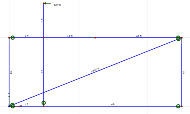
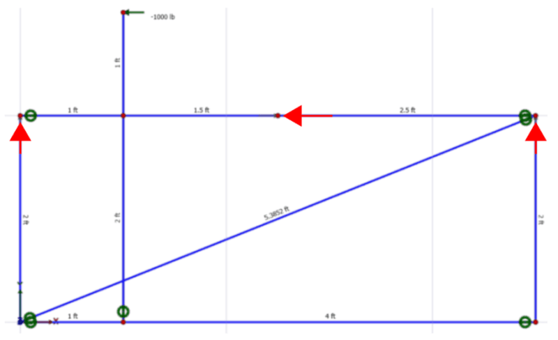
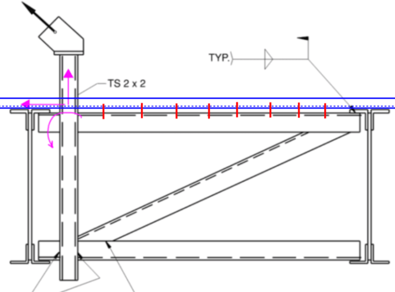
Allowing the deck to take the full lateral load, I created a model that confirms the following:

•Lateral load goes to deck (via a horizontal collector)
•Moment is taken out as (2) opposing vertical loads at each joist.

Screenshot_2024-02-14_165817_jl50je.png


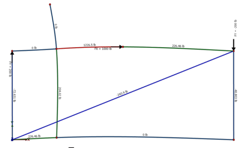
Screenshot_2024-02-14_165849_adbmfh.png


However, what I'm not understanding is why the nodes of these model don't appear to be in equilibrium. Take the node support at the upper right hand. The sum of vertical forces doesn't equal zero.

I take this model as statically indeterminate and realize there are virtual methods to solving it. Does anyone know of a quick/simplified method to determine these internal forces?

Initially, I thought the bottom horizontal would have a tension value equal to (1,000lb x 1ft)/2ft = 500 lb.
 
There's something odd going on with your model, it's not realistic for all the load to go horizontally into half the piece, (* 0 / 226 and 0/1226/226.). If you design it this way it's probably safe (upper bound theory), but it's not the actual force distribution because the vertical element is putting all the horizontal load into one side of your horizontal elements. If it's all welded the welds are equally stiff, so there should be a different load distribution on the lower and upper horizontals.

I don't see any supports (pinned) on the whole frame so those are either shut off or ?.

Draw the forces on the joints and the appropriate angles as a free-body diagram? Apply joint equilibrium.
 
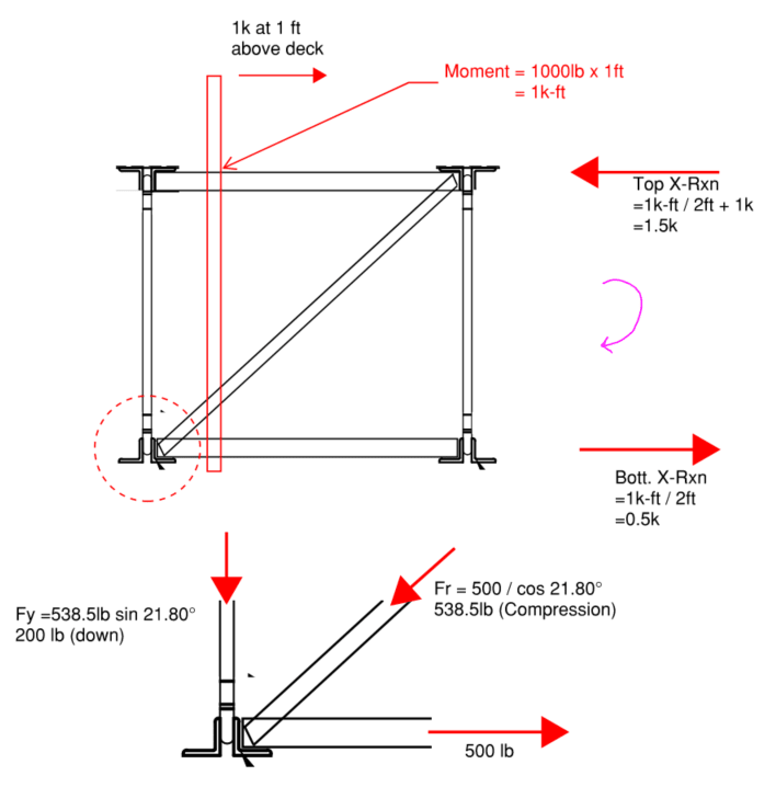
I got tired of chasing this one around. I don't think there is any direct solution the way I'd like there to be. I chalk this up to "here is an accepted method to bracing these loads", without the direct analysis to prove how it works. Maybe through testing? Maybe through historic experience? Or the super simple FBD I've shown below.

Trying to create of model of this thing was probably a waste of time. Regarding my model, the only x-reaction support is located along the top member at mid-span. This is the reason why there is zero x-component force to the left of the vertical.

Screenshot_2024-02-21_153545_fbvqrg.png


I'd much rather analyze with this simplistic and more conservative approach.

Screenshot_2024-02-21_1557502_aem1qm.png


I dump 1.5K into the roof deck with attachment to the horizontal angle. The balance of the forces 'exits' the FBD as a vertical reaction (equal and opposite) at each joist.
 
What are you using for the joist spacing then, it's a 24K series for the design concept, that I get, but I don't feel like going all arccosine on it. It should resolve into a lateral load (in the deck, which is corrugated into the plane of the page and axially stiff, and a couple on the two joists up/down to counteract the rotation induced by the 1' x 1,000 lb. load. Is it actually 1,000 lbs here or it's a "unit" load for study?
 
It was a unit load just for exercise. The joists were assumed 24" deep and spaced at 5ft c-c.

So what you're basically saying is, let all the lateral load develop into the deck and take the rotation out as a couple between two joists? That is pretty much what I have done in the simplified scenario, with the exception that I've used the bracing to take the rotation and deliver through a system of 2-force members to the joists.

Notice in my example above, the vertical load is 200 lb down at one joist (and 200 lb up at the other joist). This is a force couple = 200lb x 5ft = 1,000 ft-lb (the same as the load in the system).

I think we're on the same page but it felt like you said it differently.
 
Sounds right. 5' spacing is pretty reasonable, if you're going to use "normal" 1.5" metal deck.

In reality you don't know how exactly the forces are going to distribute out, but so long as you satisfy statics and equilibrium it should work as it's a lower bound solution? I used to know this stuff when I was doing more connection design.

This is along the lines of the argument I'm trying to invoke. It's been a while.

On the Analysis and Design of Bracing Connections, Thornton, AISC, Proceedings of the AISC national steel construction conference, 1991.

 
Ok, this Lower Bound Theorem article that you presented has got me really intrigued.

Seems like a delicate rabbit hole to be tinkering with, especially when I'm also trying to untie the mysteries of stability design (my other post), like a structural engineering version of Tom Hanks running around Vatican city.

'You make them behave the way you want them to, and they just do it.' Why are we not all talking about this WAY MORE OFTEN?
 
Have you had any academic experience with energy methods? Those show up a lot in stability design, as well.

That's the other end of the spectrum, you presume a failure mechanism and run the calcs. This will almost always over estimate the failure load, but if you presume the exact deflected shape, you'll get the same load from the other direction (statics and equilibrium). I see this a lot with fall protection (and it's kind of potentially dangerously wrong, because you almost guaranteed to overestimate the strength by presuming a failure mechanism (think plastic design of plate structures).

This concept (lower bound) shows up a lot more in connection research and design.

Think about this a minute - we've seen from research that a lot of the shear load goes into the top two bolts in a bolted connection, but we provide more and load them all equally "in design". They don't act that way in reality but it's sufficiently accurate and the bolts are sufficiently ductile that it works. The other item of note is a lot of engineers would use the "poison bolt" and design all the bolts for the lowest load allowed in that one bolt at the edge. Both approaches "work" to an acceptably safe level? Poison bolt is considered conservative as a result.

A Tale of Tearouts - Muir - Modern Steel Construction, May 2017.
 
Have you had any academic experience with energy methods?
Yes, but nothing more than the brief discussion of how work energy equations were derived. At this point I wouldn't be able to recreate the math involved to derive any of those principle equations or provide a coherent explanation of them. At best, I know how to determine deflections using the energy method of Virtual Work for trusses and beams. Even in this situation, I'll skip the integrals for beams and use a moment integral table to quickly look up some required values. As far as indeterminates, besides making safe assumptions or using computer analysis, I can apply some basics for Force Compatibility methods... and I cannot even remember if force compatibility is some derivative of the energy method...

Over my career I have found that when new information comes in, it will replace the shelf items that aren't in use. It's a maddening source of frustration, but with dwindling budgets and the need to accomplish a whole lot more responsibility with less time (the life factor), I find myself replacing these concepts with quicker ways to process the information and getting a job done efficiently.

I believe I'm at the point where most of my effort is put into 'good construction practice' as I can usually find a way to justify the design of all the elements that make the big picture. A personal goal of mine, and what I believe is the higher order of structural engineering, is understanding the stability of the system as a whole. Which is unfortunately difficult to do without the right project exposure, guidance, design example to follow, etc.. I find this particular topic much more difficult that designing any single components of a structure.

Those show up a lot in stability design, as well.
I will have to find more reading on the subject. I actually searched the text in multiple steel design textbooks I have for combinations of the words, "lower, bound, theorems" and got a handful of results that don't provide any information. I believe this subject is on the higher order of understanding that I mentioned earlier. These things are sometime easy to feel but hard to explain (like a good song). Stability is something you can feel from the age of stacking blocks... but explaining the non-linear response of a 2nd order analysis and why it's important to use reduced stiffnesses because a structure is within it's yield limit states... that's a doozy.

we've seen from research that a lot of the shear load goes into the top two bolts in a bolted connection, but we provide more and load them all equally "in design"
It's funny you bring this up because I've used this approach in many cast-in-place anchor situations before. Again, this was handled through a particular program calls "Studs" by STI. I will need to refresh myself on ACI's stance on the matter.

This engineering blog is a unique place where the people who care to know are mostly investing their own time to be here. My experience is that most individuals don't want to know, they just want a solution (which is fine). It's actually alarming to me that so many of my peers in the industry cannot hold much of a conversation when it comes to the stability chapter "C" in the AISC manual. Feels like they are relying on previous examples to know things will work.
 
Nothing more motivating than trying to engage with a peer and being greeted with apathy.

When you deal with simplified situations, the upper bound theorem and lower bound theorems both look a lot alike.

The short story on energy methods is you presume the structure fails in a certain way (think of a fixed base column loaded laterally on the strong axis, i.e. failing due to a lateral load), you presume it fails due to plastic section. M = P*L, you run the calcs and come up with a failure load. This is potentially accurate, because you presumed a failure mode. This is an upper bound on the strength of the structure. If the column has stability problems (LTB, etc), it won't "get there" in terms of strength.

For an equilibrium method, you'd run through the statics and equilibrium, and from there derive a failure load. Since you satisfied statics and equilibrium, this is a lower bound because it might be stronger.

In this case you get the same answer. An upper bound solution is >= the actual failure load, the lower bound is <= the actual failure load. There are some decent papers about the uniform force method that goes into a variety of assumed force distributions for connections, and that's where you'll probably find the most accessible literature. Like I said, it shows up a lot in connection design, and that's about the only place you'll routinely encounter it.

Poison bolt is a steel-to-steel connection concept, I've not seen it discussed in ACI, but ACI went through a whole sequence on anchor rods........
 
Through what mechanism do you dump the 1500# horizontal load into the deck? It seem like that would take a lot of deck welds working perfectly in concert (and not unzipping).
 
Through what mechanism do you dump the 1500# horizontal load into the deck?
Fasten the top horizontal member to the deck with #14 metal screws. Considering there will be a gap equal to the joist's top chord L thickness, let's say 3/16", you could determine the allowable shear load on this fastener considering (Bending + Shear ≤ 1.0), this would be around 115 lb per anchor.

Force is 1.0W, calculation done per ASD.
(1500lb x 0.6) / 115 = 8 anchors equally spaced between joists.

Limiting shear on the deck screw for a 20ga 33ksi deck would be about 200lb shear per #14 metal screw.

Screenshot_2024-02-25_222229_ruvhgb.png
 
Remember that 1,500 is a "scale" value for a 1,000 pound point load, it's not an actual value at this point. It's a "unit" load, but the unit is a kip.
 
Absolutely. JLNJ was asking about the mechanism so that was the simple illustration. I promise this isn't my first time [wink]

Again, kind of illustrates the whole point that these details are created by the institutes and people use them. But where do you draw the line?

I've sat and debated during formal review process with building officials & chief engineers in one of the most stringent jurisdictions (for wind load design) in the US, and never been asked some of the questions that I'm bringing up here.
 
I missed you're the original poster on that StrEng007, I thought it was somebody randomly wandered in.
 
lexpatrie, thanks for all the help and the additional sources of information.
 
StrEng007 said:
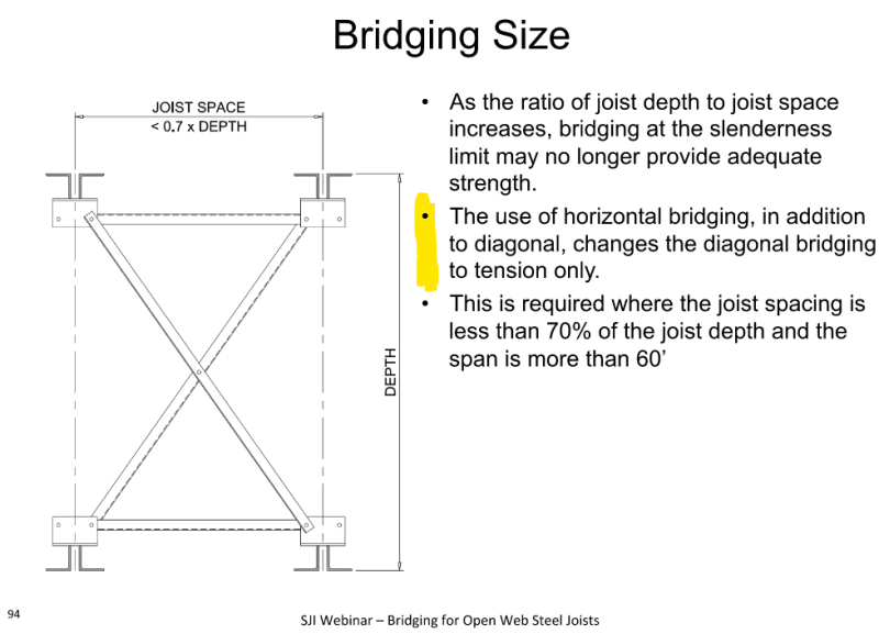
I took the following snapshots from the SJI's Technical Digest #2. When they discuss diagonal cross bracing, they mention that it's designed for tension forces ONLY.

Putting together a FBD of the brace force, where Pbr is determined by Pr/joist depth... it looks like relying on the diagonals for tension only creates forces the adjacent brace into compression. Or else the joint is unbalanced. Take Joint A for instance.

Why am I not seeing it?

I've only just started reading this thread, so I apologize if this has already been discussed. I think the distinction is that X-bridging becomes tension-only when it is used in conjunction with horizontal bridging. If x-bridging exists without horizontal bridging, then they are designed for tension and compression.
 
bones206 said:
I think the distinction is that X-bridging becomes tension-only when it is used in conjunction with horizontal bridging. If x-bridging exists without horizontal bridging, then they are designed for tension and compression.

Doesn't X-bridging without horizontal bridging only exist for erection stability and permanent bracing?

I don't see how this would be used to support applied external loads such as the case shown above. If so, then there is no mechanism to brace the bottom chord of the joist. The joist would be left with some soft of unbalance lateral load pushing it out of plane (it's strong axis).
 
Fasten the top horizontal member to the deck with #14 metal screws. Considering there will be a gap equal to the joist's top chord L thickness, let's say 3/16", IMO this is a very bad idea. Do not intentionally put fasteners in bending. Much much better to put an additional plate into the gap.
 
@StrEng007 - This is from an SJI presentation and is what I was referencing. I need to do some reading and catch up on the rest of the thread to see what you mean about external loads.

Screenshot_2024-02-29_142241_no0ylw.png
 
Status
Not open for further replies.

Part and Inventory Search

Sponsor