Continue to Site

Eng-Tips is the largest engineering community on the Internet

Intelligent Work Forums for Engineering Professionals

  • Congratulations KootK on being selected by the Eng-Tips community for having the most helpful posts in the forums last week. Way to Go!

OWSJ Identification 4

Status
Not open for further replies.

Deener

Mechanical
Aug 30, 2018
48
I have been asked to review the capacity of an existing OWSJ. I have been given dimensions and internal member sizes of the joist but no joist designation. Is there a table I can use to look up the joist designation based on the member sizes? i.e 30" deep, 3/4" square bar, 2 x 2 x 3/8" angle. Below is the sketch I received from plant maintenance. Max unfactored point load is around 400 lbs so we're exceeding the 100 lb rule. Joists are on 6' centers. No joist identification tags that I'm aware of.
image_eyfzir.png

Thanks in advance
 
Replies continue below

Recommended for you

Lots of great input. I appreciate it all. I submitted these dimensions along with the sketch to the SJI and they have identified the joist as a 30K12. The heaviest of standard joists.
TC 2.50 x 2.50 x .250
BC 2.00 x 2.00 x .250
I will heed the advice to measure all members with my own calipers, but in the meantime will proceed with an analysis to check the additional 500 lbf concentrated load. I wonder if I can pick your brains further.
1. I can use this nifty equation to calculate an average moment of inertia of the joist to check deflections. W = 137 lbs/ft in my case. I will apply service level live loads and see how deflections compare to span/260.
I_J = 26.767 (W) (L3) (10-6) where W = RED figure in the Load Table
and L = (Span – 0.33) in feet.
2. I need to check the unit stresses in each internal member. I will draw this joist up in 2D FEA and apply roof snow load as UDL, along with dead load and the concentrated 500 lb load.
3. An initial sniff check for a 41.8 psf snow load (Canadian site eh?) for joists on 6' centers gives me a UDL of 250 lb/ft. Quite close to the 280 lb/ft for total safe load in the ASD load table for this joist. Adding another 15 lb/ft for the dead load of the joist brings us to 265 lb/ft. If it's a roof with steel decking (assume 3" deep) and gravel, is there a common pressure load people typically use for the roof dead load? I'm hoping there's a standard depth of gravel used on roofs.
P.S. - the sketch does not show the proper number of panels. There are 8 full panels based on the location of the centerline. Based on the 58' span, this gives about a 6' panel length.

 
Why the need to figure out moment of inertia for the truss, if member shape and areas are readily available? I doubt the use of beam deflection equations to the truss is the correct way to do it.

Did you addressed the duel designations of web members, was it the norm for standard truss? Also, was the center line shown correctly?
 
Beam deflections equations with the moment of inertia of the truss are actually reasonably accurate. At least for a back of the napkin type calc.

Regarding roof load, for gravel ballasted tar paper roof, I typically use 25-35 psf. so that's also not looking good for you in that regard. You'd be somewhere around 70 psf total load which is 420 PLF at 6 ft centres. Seems quite a bit higher than the 280 plf you're getting from SJI. quite so much higher that I don't believe that can be correct. It is possible that the joists are at 4ft spacing instead of 6, which would nail that allowable load. Or you're getting extra conservative numbers from SJI, which is also possible.

A quick 30 second calc on my end, assuming they used the full capacity of the chords (yeah I know this is a dangerous thing but I'm just seeing if we can get close) I get that you should be pretty well right on the numbers. I.E. I'm getting that if they fully utilized the chords, you'd be at near 99% capacity. And that's not even accounting for the fact that the webs may be the governing factor.

Whatever you are wanting to add to the joist, you probably can't without upgrades. I'd be reinforcing it for the new load plus the design snow load, meaning I'd be adding chord steel and webs and welding to support the entire new load and the snow load. It ends up being minorly more steel and welding and avoid you having to take the existing stresses out of the joist prior to reinforcement.
 
Vulcraft said:
The moment of inertia of K-Series, LH-Series and DLH-Series joists in the load table can be estimated using the following equations:
IJ = 26.767 (W) (L3) (10-6) ASD, US Customary Units with W in plf and L = Span – 0.33 in feet
IJ = 2.6953 (W) (L3) (10-⁵) ASD, Metric Units with W in kN/m and L = Span -102 in mm
The equations shown above provide an approximate “gross” moment of inertia, not including the effects of shear deformation. An open web steel joist can be expected to have approximately 15 percent more deformation than a solid web member. When a conventional beam formula is used to calculate joist deflection, a factor of 1.15 should be applied to account for the web shear deformation.
 
Turns out that the joist is not a 30K12. That was SJIs guess at the closest joist. SJI thinks it is not a standard joist so I am now stuck with having to do my own analysis to determine the capacity of the joist. I did confirm the dual designation for web members. I guess my only option now is to draw the joist in FEA and investigate the loads in the members and compare to AISC limit states. Will assume all connections are pinned. I am a little disappointed that the SJI doesn't have some sort of table showing member sizes and dimensions for standard joists so we can identify them ourselves.
 
Deemer,

Can you clarify your design loads?
You stated a 41.8 psf snow load - if the dead load is somewhere between 20 and 30 psf and your joist spacing is 6 ft. o.c. that is a much higher load than the 30K12 capacity for a 58 ft. span (280 plf) as jayrod12 has suggested.


Once you know the shape and thickness, you can estimate A, and analyze using any truss design software. The trick is to get good measurement of the web members (often use non-standard shapes).
 
Do not design to AISC, design to CISC. Albeit similar, not entirely the same. Depending on the vintage of the joists the angles are likely 300MPa yield.
 
Deener,

The SJI has some great standards of practice for evaluating steel joist's (
Their technical digest 12 (link below) has some great commentary on evaluation of existing joists and methods for strengthening existing joists for additional load, quite useful.


I am unsure as to the scope of your review, nor what is creating the 400lb unfactored point load, but if it's due to a proposed RTU be sure to account for snow drift on the adjacent joists/decking as well as checking the steel decking/strengthening for any proposed openings for duct work, etc.
 
Sorry - I know i have a really good table for identifying joist sizes. I thought it was in my 60-year joist manual. Maybe not. If I can find it I'll post it.

Deener said:
Will assume all connections are pinned

Don't forget to make on of your end supports a roller, unless it's connected to something that really won't deflect. (It may be welded, but if the beam or wall can move outward, it will and the support becomes a roller).
 
Before going your own analysis to determine the capacity of the joist you could check with the owner, City or Municipality with any drawings they may have available for the building.
I'd re-check your measurements on the joists and re-submit to SJI with any discrepancies and look on every single joist in the building for a tag hanging from the joist (even if steel joists are used for the floor system). I've had numerous times where they say its a custom joist but after digging further with the City/Municipality I was able to find out the joist... Given it closely resembles a K series steel joist, which that series started to be manufactured after 1986 I find it highly unlikely that the City or Municipality would allow a joist to be constructed by a company who is not certified by the SJI.. As we are in Canada there could be a limited number of steel joist manufactures in your area, i've had luck previously calling manufactures and discussing the site and they've had information on the site on file. Canam Canada may be a good place to start, they have information on the strength of steel they've used for they're joists dependent on the year with a CSA at the bottom if it cannot be identified (
If you do choose to do your own analysis, the welding electrodes used could drastically change the capacity of the joists.
 
Hey guys,
I have gone ahead with my own analysis of the custom joist. Canam has a good reference to the SJI standard specification for joists on their website (I'm using SkyCiv to analyze the axial and bending forces (top chord only) in my members. One end pin and one end roller. As a reminder, these are the member sizes for the 30" deep Warren truss.
Top chord - 3" x 3" x 3/8" back to back angle
Bottom chord = 2" x 2" x 3/8" back to back angle
Vertical web members = 3/4" square bar
Diagonal web tension members = 3/4" square bar
Diagonal web compression members = 1" x 1" x 1/4" back to back angle

Joists are on 6' centers. Loading is as follows
Snow load 41.8 psf which equates to 20.9 lbf/in on each truss.
Roof dead load is 30 psf which equates to 15.0 lbf/in on each truss.
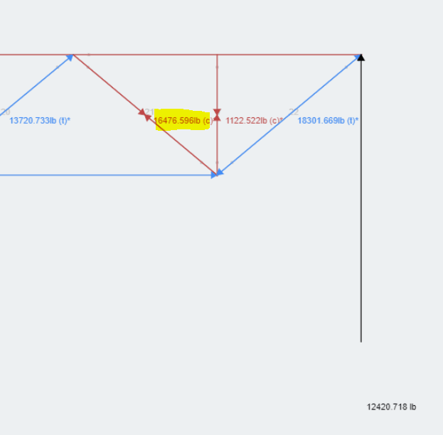
Self weight of the truss. Below is a picture of the displacement along with the reaction forces as a sniff check.
image_bzyfiv.png

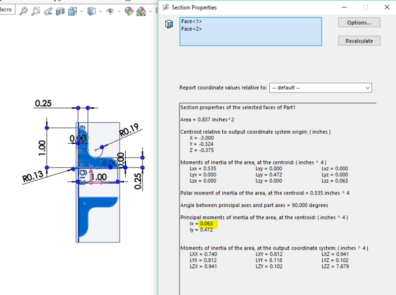
With just these loads alone, I get a peak compressive force in the web angles of about 16 kip (close to the support point as expected). Looking at the slenderness ratio of a single 1" x 1" x 1/4" web angles (length = 46.8in, r = 0.18), it is beyond 200. I'll need to go to site to confirm but I'm thinking these back to back angles must be connected to one another to act as a single member in buckling. If that is the case, and they are spaced 3/4" apart due to the square bar member, the combined radius of gyration for the two members is 0.27 in (I = 0.063 in^4, A = 0.83 in^2). This still leads to a critical buckling stress below 9.0 ksi. Stress in the angles is about 19.0 ksi. Something must be wrong with one of my assumptions if these members are failing so badly under what should be their design loads.
image_by3n0w.png

image_v4vy0o.png
 
Roof Dead Load = 30psf. What kind of roof do you have? A lot of industrial facilities/manufacturing plants have little more than steel deck on their joists. I work in one such facility. For the purpose of looking at roof dead load on the joists, I would use 2psf.

Also, be careful with material properties in SkyCiv. I use the program, too (and like it - great bang for the buck), but it has a few quirks. For instance, their standard "structural steel" material property isn't really analogous to anything I've ever designed with. Did you find and apply the appropriate material spec from the library or make your own from historical resources?
 
Both loads seem too high, are they factored?
 
42 PSF snow can happen in many locations here north of the border. And 30 psf for a ballasted roof (i.e. tar and gravel) is not outside the realm of normal. I tend to agree with the design loads.

Regarding the analysis, I am not familiar with that program. For the material yield stress I would go no higher than 300 MPa (44 ksi).
 
jayrod - I agree that kind of roof would have a 30psf dead load. It's an uncommon roof type around here (potential for high winds + ballasted roof = projectile hazards), so I just wanted to be sure it wasn't an over conservative estimate.
 
Snow loads can be checked using this link --> It is a gravel roof. Assuming a dry gravel density of about 105 lb/ft^3, it would take about 3" of gravel to get that dead load. Most likely a conservative amount. Even if I decrease the amount of gravel to 1", my UDL on the joist goes to about 4.5 lbf/in. Axial load in the compressive web member goes down to 12 kip and it still fails. My only guess is that I've been given the wrong information on the truss somehow. Regarding skyciv, I'm only using it to get the loads in the members so youngs modulus is my most important input and it's set at a normal 29000 ksi. I am basing my checks on 44 ksi material yield.
 
Something must be wrong here. Capacity of K-series (ASD):

Yield strength 50 kai
For span = 58', use 30K12, uniform load = 290 plf
For span = 40', use 30K12, uniform load = 438 plf

OP's load = (42+30)*6 = 432 klf. Either the span is way too long, the load way too high, or the measurement is incorrect.
 
Deener - since I'm in the US (as are many others on this thread) can you clarify to me whether your loads are service level (unfactored) or ultimate level (factored) loads?


I believe those would be service loads, the dead load for sure is SLS level (service). Depending on the location in Canada, I wouldn't be surprised if the snow load was service level as well.
 
Status
Not open for further replies.

Part and Inventory Search

Sponsor