Continue to Site

Eng-Tips is the largest engineering community on the Internet

Intelligent Work Forums for Engineering Professionals

  • Congratulations KootK on being selected by the Eng-Tips community for having the most helpful posts in the forums last week. Way to Go!

P-Y Curves

Status
Not open for further replies.

GB1000

Structural
Oct 31, 2017
28
I'm after some assistance please. Firstly I've just started to get into pile design. Initally started with Broms to Brinch Hansen and now P-Y Curves. But I'll be honest, its a mind bender. I understand the concept in the sense that soil reistance is related to the delfection of the pile. however what is mind boggling me is:-

When a p-y curve is produced, is the P the resistance? defined as kN/m. but how does this relate to a ultisation ration? i.e. I have a set of springs all giving varying soil reistance kN/m, I'm trying to visualise this what is the collapse soil resitance figure?

Hope this makes sense and any advise on where to start would be greatly appreciated
 
Replies continue below

Recommended for you

I generally refer to "Lateral Load Analysis of Single Piles and Drilled Shafts," by Duncan, Evans Jr., and Ooi.

Upper case P is the load at the top of the pile, in kN. Lower case p is the soil reaction, in kN/m.

DaveAtkins
 
Can you explain your question a bit more please?
 
You judge utilisation for the entire pile, not individual springs. Increase the load applied at the pile head until the capacity is reached - that's the ultimate capacity. Then apply your factor of safety (if using allowable load design) or capacity reduction factor (limit state design) to get design capacity. Utilisation is design load divided by design capacity.

The analysis software could report ultimate capacity in a few ways. It might converge at a load of X, but fail to converge at 1.01*X. Or it might report an unrealistic deflection such as 1000 metres (or a million) indicating that the available soil capacity was insufficient to resist the applied load. As you increase the load, note down the deflection at the pile head and check it looks as expected - linear at low loads, then increasingly nonlinear, until failure when small load increase causes large additional deflection.
 
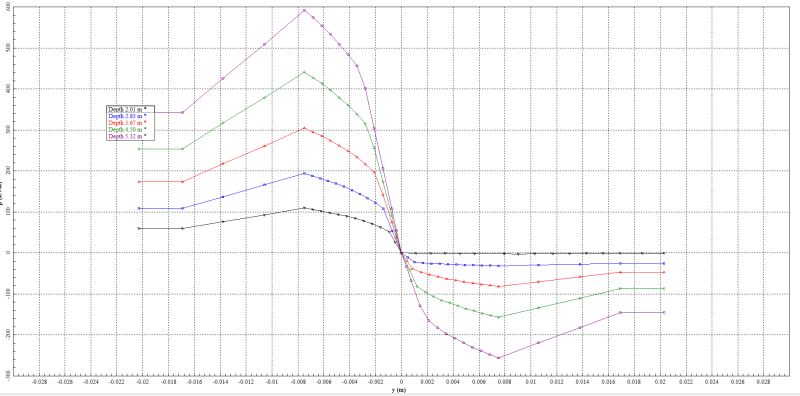
Do you know why on the following graph why deflection does not ago above 22mm? I'm assuming this is something to do with the limit of the soil, but this figure will not change depending on any imput I use. Note this is from PYWALL from a colleague which popped it in the software. but to be honest I think she is struggling to understand as well
Untitled_xyp4tr.png
 
Apolgies the vertical line is the soil resistance and y is obvioulsy the deflection
 
I've never used PYWALL so not sure; hopefully someone else can help. I did look through the manual which is available online for about 5 minutes. Figure 4.12 on page 4-12 (2019 version manual) shows the PY curves ending at 0.55 inches which is 14mm. In both your graph and the manual, there are only two points at the final P value. Perhaps when the deflection is larger than the last value on the PY curve, the software assumes 'ductile' soil behavior, so uses the 22mm P force for any deflection >22mm. If this is the case, there is no need for the PY curve to be defined any further.
 
Thanks Steve, yes this is I was thinking that after the two points on the y deflection there is no point to carry on as it will always be 22mm.

However I'm not quite sure what that means though in terms of design and resistance of a pile. Is the p-ycurve just stating the soil and pile will collapse anything above 22mm? I don't know? Even when you change all properties of the wall, I.e ht etc it just seems to be limited 22mm.

I'm definately missing something.
 
If it isn't explained in the manual, run some test analyses to see how the software behaves.

GB1000 said:
I was thinking that after the two points on the y deflection there is no point to carry on as it will always be 22mm.

I think that if the pile deflects more than 22mm at any given point, one of the following will happen:

A) The soil reaction at that point will remain the same as it was at 22mm regardless if how far the pile deflects; or

B) The soil reaction will become zero at that point (local overstress of the soil). This doesn't necessarily mean that the pile fails because other springs may still provide sufficient support to the pile. Note that the available soil resistance increases with depth in the curves that you posted earlier. You can also easily picture loose soil at the ground surface being pushed away from the pile without any consequence if the pile is embedded deep enough.

So in case A, there is no point continuing the curve beyond 22mm as it would just be a horizontal line but the software is written to assume this anyway. In case B, 22mm is the point of *local* soil failure - but once again I'll say that this isn't necessarily failure of the entire pile. It would however be good practice to increase the embedment length or pile diameter if necessary to limit local failure to a small area near the ground surface.

 
Thanks Steve, Its great to get another Engineers thoughts on this.

I've looked into this abit more and I believe the reason it justs stops at 22mm is the fact the soil resistance remains the same. so even though the deflection can go up the soil resistance will stay the same. hence the two points on the y-graph. This is what you state in your point (A).

So lets just assume we are correct with point A, Exactly what does this mean in terms of F.O.S in the soil and resistance. This is my understanding: -

1. The 'pile' is designed obtaining the moments and shear in the pile, then using your code of your preference you design the pile with load factors and reduction factors. I believe this is straight forward enough.
2. The resistance to overturning (deflection) is a function of the soil resitance, width of pile etc and 'allowable deflection' of the pile. There are two ways to approach this method

1. you factor the loads up and check the deflection
2. you limit the deflection to what is acceptable and give yourself a F.O.S on the deflection.
3. The soil reistance (kN/m) is effectivley the resistance of the soil. for example if you divide the pile by an increment (this is effectivley the spring centres). Then for the above example lets just say at a depth of 5.32m, the soil resistance is 180kN/m (approx), lets say the spring centres are 0.1m. Then at that spring location the force is 180kN/m * 0.1m = 18kN.

The whole theory of the P-Y curves is a fucntion of the deflection of the pile and what is accetable. Its NOT this is the force on the pile, this is the allowable bearing capacity and hence here is your F.O.S. This is what I'm believing to think is correct???????

Your thoughts would be greatly appreciated.

 
Since I now suspect you're in Australia, the simple answer is that you need to design to AS 2159. This is a limit state code so you check serviceability (deflections) under serviceability loads, then check ultimate resistance under the ULS factored loads. The ULS check might also consider deflection if the supported structure could collapse due to excessive pile deflection.

In AS 2159, see clause 4.4.7:
"...the design ultimate geotechnical strength for ‘short pile’ failure, in which the ultimate lateral resistance of the soil surrounding the pile is fully mobilized along the entire length of the pile."

This is what I referred to in my first post. In PYWALL, increase the applied load until the pile falls over, ignoring the bending moments and shear stresses etc. You want to find out what load wold push a strong pile over, ie cause soil failure. This is the ultimate geotechnical strength. Then calculate the capacity reduction factor using the AS 2159 procedure, and multiply the ultimate strength by the capacity reduction factor to get design strength. Design strength has to be greater than factored ULS loading. Only after you've finalised the geotechnical design would you finalise the structural design as the moments and shears depend on the geotechnical analysis.

The above procedure is essentially the same as for a steel beam (for example). You calculate the ultimate capacity (eg section capacity Ms), then apply the capacity reduction factor (phi = 0.9) to get the design strength. The main difference is that phi has to be calculated for pile design because the ground isn't a manufactured product like a steel beam. There's a lot more variability and hence the reduction factor depends on how good the site investigation was, how accurate the design method is (a lot less than calculating steel beam strength), whether you'll do pile testing or not, and how important the supported structure is.


steveh49 said:
increase the applied load until the pile falls over, ignoring the bending moments and shear stresses etc.

This only works for a "short" pile. If the pile is "long" it will never fall over. The failure mechanism for a long pile is structural, not geotechnical.
 
Status
Not open for further replies.

Part and Inventory Search

Sponsor