Continue to Site

Eng-Tips is the largest engineering community on the Internet

Intelligent Work Forums for Engineering Professionals

  • Congratulations KootK on being selected by the Eng-Tips community for having the most helpful posts in the forums last week. Way to Go!

Parallel beams bracing 8

Status
Not open for further replies.

Italo01

Structural
Sep 4, 2021
169
Hello Guys,

I have the following frame( Showing only the necessary part of the structure for the understanding of the problem). The Span is 9,00m(30ft) and the intermediate beam is suporting non-structural masonry. In order to increase the stiffness of the frame, share a part of the load of the intermediate to the top beam and give better suport to the masonry wall, i introduced the green ties. My question is, if i utilize rigid connections, the ties will brace the beams for LTB(Torsional bracing)?
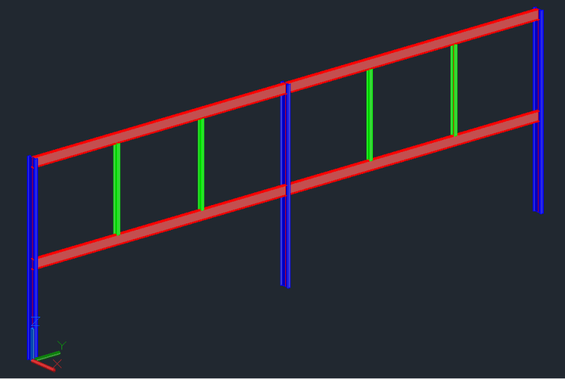
Frame_jwojzr.png


Is there a document that deals with this kind of bracing?

I don't think that it won't be as effective as a traditional bracing where the beams are on the same horizontal plane but may be sufficiente.

Thanks in advance.
 
Replies continue below

Recommended for you

Kootk said:
Is there not a roof diaphragm that will brace the upper beam laterally?

Yes, there is a roof but the roof will stop before the gutter, which will be supported by the last purlin and bu the upper beam. This gutter won't have enough stiffness to brace the beam.
 
Kootk, Since i became aware of eng-tips and started participating i admired your work a lot. You do what i always tried to do that is understand the theory of structural analysis and design and study all of its aspects, of course that on another level. I would like to know if you could contact me via email (italo.reboucas01@gmail.com) so i can ask you some questions related to this approach you have with respect to engineering.

I'm not gonna send you a lot of messages nor will i send this detailed questions that i post on this forum and leave it. Its just that sometimes is frustrating that most enginners that i know here don`t have the same approach ("Just push some buttons on a random software and its fine") and i`d like to have some talk with someone so qualified.

Please, disregard this request if it's too incovenient.

 
Italo01 said:
With respect to the second approach, i changed it not because i didn't feel confident about the first approach but because i could reduce considerably the weight of the steel, since the moments are much smaller and the stiffness is much greater.

Sure, if your reason for the change is just improved efficiency for carry gravity load, that certainly works for me.

Italo01 said:
Yes, there is a roof but the roof will stop before the gutter, which will be supported by the last purlin and bu the upper beam. This gutter won't have enough stiffness to brace the beam.

I can't say that I've ever seen a gutter on the interior side of an exterior wall. That said, there's a great deal that I 've never seen, including Brazil.

Italo01 said:
Please, disregard this request if it's too incovenient.

Not to worry, I enjoy relationships of that kind and deliberately cultivate them here on the forum. I'll reach out.
 
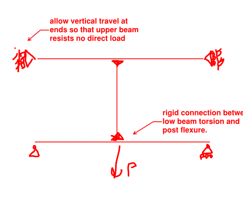
@Italo01: If you're feeling sporting, I feel that you could run the model shown below to demonstrate "proof of concept" for your proposed bracing scheme. When in doubt... strip stuff out. Compare a run with the frame as shown below to another run with just the low beam all by itself.

c01_kdpmpi.png
 
Hi CDLD, thank you for your help but i think that this moments, and consequently the beam forces, will be computed automatically by the model since they occur because of the initial out-of-straightness which was included in the model.
 
Kootk, i'll try it. I did some models to try to model these effects but this one you showed is really simple and clear, since the beam will continue simply supported and the bending moment diagram regular.

Thanks.
 
Kootk, i did what you suggested and the results are in good agreement with the theory of beam bracing.

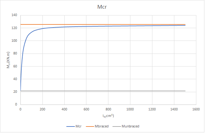
I analyzed a W150x13 (W6x8,5 in imperial units) with 3000mm of lenght and two bracing(Lb=1000mm). The top beam is equal and these are spaced also by 3000mm. The following chart shows the elastic critical moment for LTB for varying values of Ib(Moment of inertia of the bracings out-of-plane. (The gray and orange lines show, respectively, the critical moment for unbraced and braced beams).

PlotMcr_a31rkl.png


Utilizing the methodology proposed by Yura i found that Ib necessary for bracing is 110cm[sup]4[/sup], which i think its in good agreement with the results since Mcr is equal to 93% of the value for complete bracing.

The model didn't consider the position of bracing, which I think that can be done by the introduction of rigid bars with length equal to half of the beam height, and the stiffness of the connection, which can be done by the change of the brace stiffness to a equivalent stiffness.
 
Italo01 said:
Kootk, i did what you suggested and the results are in good agreement with the theory of beam bracing.

That's great work Italo01. Thank you, both for taking the time to investigate this and for reporting back on it.
 
Status
Not open for further replies.

Part and Inventory Search

Sponsor