Eng-Tips is the largest engineering community on the Internet

Intelligent Work Forums for Engineering Professionals

Parallel Cable imbalance load 2

Status
Not open for further replies.

vithanidevesh

Electrical
Aug 27, 2023
9
0
0
IN
Hi
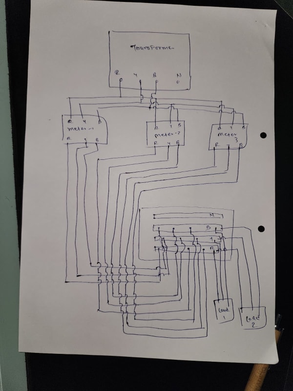
I have following system installed
Govt supplied transformer is incoming supply
From transformer - there are 3 energy meters installed. I have laid 3 cables 3.5 core 150 sq mm aluminum cable (length around 5 meter each) and all of them are connected to one Busbar chamber from there load is distributed

Now when I check current, following is my readings

Cable 1 - 103/133/160
Cable 2 - 144/135/104
Cable 3 - 125/103/120

Main issue is due to this, my maximum demand is crossing assigned limit and i am getting one meter reading higher than other 2

How to solve this and make even distribution ?
 
Replies continue below

Recommended for you

Post actually would fit better in the transmission & distribution forum, but since you've put it here, don't bother moving it.

I may be way off base, but what are the readings at zero load? I'm asking so as to find out if there's an inherent mutual induction issue in your installation.

CR

"As iron sharpens iron, so one person sharpens another." [Proverbs 27:17, NIV]
 
I am new here - Not able to find how to move to appropriate section. I didnt checked current in No load - will check as soon as I get chance, but I checked Output load and its matching with input load

I was reading old posts here and found it may be related to skin effect - unfortunately thread i was reading was closed so I couldnt ask there
 
Have you checked the voltages?
The unbalanced currents may be due to magnetic interaction between the cables.
You may have some metering error if you are measuring with a clamp-on ammeter.
Are you able to post a sketch or picture of the cables?
Is the transformer secondary wye or delta, transformer primary?

--------------------
Ohm's law
Not just a good idea;
It's the LAW!
 
The problem is “length around 5 meter each”. All three conductors on each phase have to be exactly the length and each termination has to add exactly the same impedance.

I’ll see your silver lining and raise you two black clouds. - Protection Operations
 
1) Transformer is Delta - Star
2) Does 5 meter length is too much ? I have in same plant 70 sq mm cable supplying to motor have 2 run 50 meters each and it hardly have 2-3 amp diff
3) Clamp meter is showing correct as same current is measured in Electronic energy meter (Govt installed)

Will share sketch tomorrow

Cables may have some difference as its installed at different intervals so there may be chances of diff manufactue

I can change cables and planning to replace 150 sq mm AL cable with 95 Sq mm copper flexible single core cable - each phase have one core only But thats a costly option and I want to be sure cable replacement is going to solve my issue
 
What are your loads?
Motors?
Motors with VFDs?
Electronic power supplies?
Is each cable metered separately?
From one part of your description it seems as if the cables are going from a transformer to a common bus. (all of them are connected to one Busbar)
From another part of your description it seems as if the cables are going from a transformer to separate loads.( there are 3 energy meters installed.)
I can change cables
Why?
The cables don't cause current.
The cables convey current caused by connected loads.
Tec-Tip: Use the IMAGE feature of this site.
You must first get a file containing an image onto your computer. Control-Shift-S will allow you to take a screen shot and save it to your computer, usually in the download folder.
Screenshot_2023-08-27_at_11-51-56_Parallel_Cable_imbalance_load_-_Electric_motors_generators_engineering_-_Eng-Tips_eyoplj.png

Click on the Image Icon and then click on Browse. That will take you to your download folder and the most recent screen shot will be at the top of the list. If the file is already on your computer rather than a screen shot, you may navigate through your file folders until you locate the file.
Click on the file of the image that you want.
Click on "Open"
Wait...........
When the file has completed uploading, the "Done" box at the lower right will become active and will change colour.
Click done.
You may click "Preview at any time to see how your post or partial post will look when posted.
Screenshot_2023-08-27_at_12-00-51_Parallel_Cable_imbalance_load_-_Electric_motors_generators_engineering_-_Eng-Tips_vikewe.png
xxxxxxx
Screenshot_2023-08-27_at_12-05-59_Parallel_Cable_imbalance_load_-_Electric_motors_generators_engineering_-_Eng-Tips_kozk4z.png

Please post a scan or a picture of some recent utility bills.
You may have a Power Factor issue.
A poor power factor increases your demand.
A poor power factor may be improved.

--------------------
Ohm's law
Not just a good idea;
It's the LAW!
 
David's comment on the cable length was my first thought as well. For cables in parallel, short cables are more of a problem than longer ones for unequal current division. Any difference in length is a bigger percentage difference in the total cable impedance, so this causes more imbalance. For long runs, the length difference is generally a smaller percentage of the total length. Also, physical arrangement can change the inductive reactance of the cables even when they are the same length.
 
WhatsApp_Image_2023-08-28_at_10.21.30_lvollp.jpg


Image attached - sorry for bad drawing
@warros
1)Its textile manufacture plant - load is heaters/motor/motor with vfd
2)Cables are going to bus and then load is connected thorough common bus - this was done to maintain equal load to all 3 meters

Why I want to change cables ? - Because length may have slight variation so as make of the cable. I want to replace and lay exact same length and same make cable so that cable property is match

Power factor issue is not there as I have already installed automatic power factor correction panel and its maintaining PF near 0.99

And its not that one cable is taking high and other is low. Its phase vise unbalance

Cable 1 - 103/133/160 - Here R has low and B has high
Cable 2 - 144/135/104 - Here R has high and B has low
Cable 3 - 125/103/120 - Here Y have low current


Regards,
Devesh
 
That is a new one on me. Am I really seeing 3 revenue meters in parallel, and the utility apparently not billing it all as one load?
Looks to me like the combined demand is the one that would matter, the utility shouldn't really care much about how much current each
meter carries (within ratings)
 
Sum of currents in each phase is almost same at around 370 to 380 A. How that would raise your input demand? The metering CT measures all currents at one point at the point of supply

All these readings are taken at slightly lower load, I am running at plant at 80% because of this load issue

If you can check in cable 1, its B phase is going 160Amps. My LT connection allow max 100 KW and even if it cross 100 in one phase, I will get penalty and if it crosses 4 times in a year, utility company will force me to take HT connection which is costly and due to some accounting issue, I can not

Am I really seeing 3 revenue meters in parallel, and the utility apparently not billing it all as one load?
Looks to me like the combined demand is the one that would matter, the utility shouldn't really care much about how much current each
meter carries (within ratings)

No - I am billed for 3 meters separately. Each meter is registered for separate entity. It doesnt matter until my demand cross to 100KW which is limit for LT connection. For HT, I have to surrender all 3 meters and will have to leave govt subsidy benefits which are due

Is there a way to reduce this unbalance ?
If I separate out each conductor from cable and group them phase by phase, will it change something or will make things worse ?
 
There is an important question that has not been answered.
What are your individual phase voltages.
No amount of cable changing will correct a voltage unbalance.
IF the problem is cable impedances (due to the arrangement of the conductors) then grouping phases may make things worse.
possible mitigation measures:
IF the problem is cable impedances, replace with three core (plus ground) cables. IF the problem is cable impedances from the transformer to the meters and three equal three core cables from the meters to the load bus.
Alternately, three equal cables from the transformer to the load bus and cut in the meters at any point.

But, things to check;
These checks will be affected by voltage unbalance do check voltage first.
Check the current balance of each load. If all loads are running high on the same phase, that is another good indication of voltage unbalance.
If then voltage is good, and some loads have one phase current high, roll the connections (A-B, B-C, C-A) so that the highest phase current is on another phase.

Thinking outside the box, you may try increasing the impedance of the high current conductors.
Many years ago, in text books that were old then, there was a device called a wire-less reactor that was used to matchtransformer impedances so that transformers of different impedances could be connected in parallel and share the load properly.
The wire-less reactor was a stack of iron laminations similar to a transformer core.
One secondary conductor was passed through the wire-less reactor to increase the effective reactance of the transformer.
Good luck sourcing a wire-less reactor today, BUT, there may be an even better alternative.
Disclaimer; this will be a test based on first principles and if you try this method, then you tell us if it works.
Pass a higher current through the window of a window type CT. Select a resistor that will pass rated secondary current through the CT secondary.
Check the results. If there is a reduction of current, then consider adding more CTs.
Note: This is to correct cable impedances.
This may correct voltage unbalances but if the utility corrects the voltage unbalances or if the voltage unbalances change as other loads on the distribution circuit change it may, at times, drive the current on other phases high.

I am out of time. When I get back I will discuss a fairly economical, "Roll Your Own" load shedding scheme.

--------------------
Ohm's law
Not just a good idea;
It's the LAW!
 
Mr. vithanidevesh (Electrical)(OP)27 Aug 23 11:04
".... Govt supplied transformer is incoming supply to .... 3 energy meters installed. I have laid 3 cables 3.5 core 150 sq mm aluminum cable (length around 5 meter each) and all of them are connected to one Busbar chamber from there load is distributed ....... following is my readings Cable 1 - 103/133/160, Cable 2 - 144/135/104,Cable 3 - 125/103/120 ...."
1. there are numerous learned advice posted. I wish to add the following for your consideration.
2. Visually check that the three cables from the Trafo to the meters are Cable 1 is [1L1, 1L2, 1L3] and Cable 2 is [2L1, 2L2, 2L3] ..... in trifold form. NOT, [1L1+2L1+3L1], [1L2+2L2+3L2] .....
3. Check cable from meter to busbar. Cable 1 comprising of [1L1+1L2+1L3+1N], Cable 2 comprising of [2L1+2L2+2L3+2N}...... Each cable comprising of [[L1,L2,L3,N] throughout the whole length.
4. As Al is used for cable lugs, cables and busbars, check the workmanship. Retighten every contact point to the "correct" torque!. Please furnish the bolt size and the torque used.
4.1 Observe whether any changes in the current, as compared to the initial readings.
4.2 Roll the phases and observe the current as compared to the initial readings.
5. In usual case, it is not required to change the cables, as the three cores+N are of equal length.
6 . However, the cables to meter 2 and 3 current may differ from that of meter 1, as they could be of sight difference in length. What we tried to achieve is L1, L2, L3 in a 3c cable is about equal.
Che Kuan Yau (Singapore)
 
Nope, all of the L1s have to be exactly the same length (same impedance) and all of the L2 have to be exactly the same length as well as all of the L3s. But there can be some variation between the L1s and the L2s and the L3s. The differences between phases will be determined entirely by the load, but the distribution of currents of any given phase is entirely driven by the difference in impedance between the paths.

I’ll see your silver lining and raise you two black clouds. - Protection Operations
 
Your demand is coming from your load, not from the unevenly loaded cables (whose sums in each phase are more or less equal anyways).

Is it legal to have 3 connections in 3 different names under one premises just to beat the system? Tread carefully.

Muthu
 
Status
Not open for further replies.
Back
Top