Eng-Tips is the largest engineering community on the Internet

Intelligent Work Forums for Engineering Professionals

Parallel Cable imbalance load 2

Status
Not open for further replies.

vithanidevesh

Electrical
Aug 27, 2023
9
0
0
IN
Hi
I have following system installed
Govt supplied transformer is incoming supply
From transformer - there are 3 energy meters installed. I have laid 3 cables 3.5 core 150 sq mm aluminum cable (length around 5 meter each) and all of them are connected to one Busbar chamber from there load is distributed

Now when I check current, following is my readings

Cable 1 - 103/133/160
Cable 2 - 144/135/104
Cable 3 - 125/103/120

Main issue is due to this, my maximum demand is crossing assigned limit and i am getting one meter reading higher than other 2

How to solve this and make even distribution ?
 
Replies continue below

Recommended for you

I am searching for any logical reason to support separate billing on the basis of individual cable current rather than the sum of three cables in a phase. Total current in each phase needs to be considered along with voltages to determine kw, kvar, kva

Did edison guess it right?
 
There is an important question that has not been answered.
What are your individual phase voltages.

Do you want to consider load shedding?

--------------------
Ohm's law
Not just a good idea;
It's the LAW!
 
The whole setup is screwy, but that doesn't change the driving electrical properties. If there are three parallel paths from the transformer to the load bus, even if through three different meters, the current split between conductors of the same phase will be determined by the difference of impedance. At "around 5 meters" small differences in lengths can have noticeable impacts on how the current splits.

I’ll see your silver lining and raise you two black clouds. - Protection Operations
 
My thoughts David:
Cable 1 - 103/133/160 = Over 50% difference.
I find that hard to reconcile with impedance difference.
It is too much.
The OP contemplates grouping the phases.
That may imply that the cable groups are now ABC, ABC ABC.
If the connections were rolled at the meters, and if the current was checked at the meters, that would explain how the current differences don't line up.
If we take each set of measurements in the order of lowest current, intermediate current and highest current, that would clearly point to a voltage issue.
Rolled connections at the meter would explain this.


FOR THE THIRD DAM TIME WHAT ARE THE VOLTAGES!


--------------------
Ohm's law
Not just a good idea;
It's the LAW!
 
Cable 1 - 103/133/160
Cable 2 - 144/135/104
Cable 3 - 125/103/120
I interpret it as each cable carries 3 phases.
If there is an error in labeling the phases at the point of measurement as Bill is suggesting, then I think it needs to be more than once because the lowest phase shows up in any of the three positions (first, middle or last).

So it's either
[ul]
[li]actual voltage or total current imbalance AND two measurement errors[/li]
[li]___ OR[/li]
[li]impedance imbalance.[/li]
[/ul]
Occam's razor seems to point to the latter but I don't rule out either option (and I'm always hesitaant to disagree with Bill!)

I might be mistaken, but it seems like this is small-cross-section cable whose impedance is often dominated by resistance (while larger cable impedance tends to be dominated by inductive effects). And it's three phases are run in one cable which further reduces inductive effects. So my thought is resistance is most important for current splitting among parallel paths here. So maybe do a thermography scan of terminations check for any toasty hot connections.
 
For the fourth time;
Knowing the voltages will put a quick end to this part of the discussion.
Such a large unbalance on three sets of cables may be is stretching coincidence.
Rolled cables and unbalanced cables may be more credible.
I may be wrong, it happens.
If a cable in one set had a higher impedance than its paired conductors, the current deficit would be split between the other two groups more or less equally.
The last time I saw a bad connection on an aluminum cable it was easy to locate and identify by the wisps of smoke.
In my experience, bad connections with aluminum tend to escalate fairly quickly.

Possibly, when the last meter was installed, the cable run was 50% or more longer than the other cables.
If someone tried to balance out the difference by reconnecting so that the much longer cables were distributed amongst the three meters, that would explain the discrepancies, and could be easily corrected by reconnecting the cables.
Despairing of receiving voltage information, I am moving on to the next possible cause.

IF the VOLTAGES are EQUAL, then, as Pete suggested, there may be more than one wiring issue.
Partial magnetic encirclement may be a factor.

As for the three meters,
I imagine that the utility either has no say or else doesn't know that three meter outputs are being paralleled.
It is what it is, don't fight the problem.
I spent over ten years in a jurisdiction where the utility was prohibited by law from inspecting or setting any standards for anything downstream of the revenue meters.


--------------------
Ohm's law
Not just a good idea;
It's the LAW!
 
PS, a 3% voltage difference may result in a 9% current difference.

--------------------
Ohm's law
Not just a good idea;
It's the LAW!
 
In support of David.
The best that you can do with what you have is to connect all of the longest cables to A phase.
Connect all of the shortest cables to B phase.
Connect the intermediate cables to C phase.
Alternatively, if the voltage on one phase is chronically high, connect the longest cables in that phase and let the extra impedance reduce the unbalance at your motors and partially mitigate circulating rotor currents.

--------------------
Ohm's law
Not just a good idea;
It's the LAW!
 
Total currents per phase the currents are balanced 372,371,384 A.
Phase arguments are 0,-125,+120 degrees.
The total homopolar current is elevated [more than 10%] but it is not balanced per cable. It has to be the same argument and 1/3 of total.
In my opinion, the currents are mixed in a way [the currents pass more than once through the measure point].
 
We had the same problem while constructing a temporary cable connection to a 75MW gas turbine after water caused the existing non-segregated bus to blow up. We had like 10 750MCM cables in parallel on each phase. The current was significantly different in each cable. What we suspected was small differences in length and location would have changes in the resistance and particularly the reactance. We just lived with it, it was temporary.
You might consider rolling the locations so each cable occupies the same geometric location for the same length (they do this in many large generators stator bars, it’s called Roebelling) or maybe group the difference phases together to reduce the magnetic effects (grouping phases will tend to cancel the magnetic field around the cables which could reduce the imbalance)
Just some thoughts, good luck.
 
Sorry for late reply

1) Voltage I measured previously, didn't have much noticeable difference - I measured with standard multimeter available with me. I will share reading once again when I will get shutdown - As I have to switch OFF individual feeders to measure exact voltage
2) There is no measurement error because electronic energy meter is showing same reading I am measuring with my clamp meter
3) Connecting phase wise - Longest to one etc will be slight difficult as it will remove my grouping - as of now each cable have all 3 phases while regrouping will create each cable with one phase
4) Even, if I replace cable with exact same length - transformer to meter to SFU box is in Utility scope so it will have some difference
5) there is no physical sign of heating - I checked multiple times, even changed all lugs and connection when Noticed such diff first time
6) what I can do is, if regrouping is required, i have to separate out each conductor of the cable and re arrange everything, or else I can replace SFU to busbar cables with exact same length and same size

What if I connect some small load - for example 10-12 kw load directly to meter 3 SFU rather than going through busbar ? will it increase load in cable 3 and decrease in cable 1 ?

Do you think It may have internal circulating current as well ? Although I measured load current and its matching with input current sum but there is switching load (heaters) so currents keep fluctuating so there may be some error
 
How long are the cables from the transformer to the meters?
How are the cables arranged from the transformer to the meters?
Are any cables or conductors encircled by ferrous material?
Are there any short lengths of conduit?
Do all conductors enter steel or iron enclosures through the same opening?​
Where are you measuring the currents?
this is important to discriminate between cable unbalance versus load imbalance.
Are you able to check at the meters that A phase is in the same position on each meter?​
The phase arrangements may be rolled at the meters.
If the phases at the meters are, from left to right, A-B-C, B-C-A and C-A-B, the meters will work perfectly well, but load unbalance will look like cable unbalance.
Loads; Do you have many single phase loads?
Cable imbalance:
Three core cables tend to be inherently balanced for resistance and reactance.
Differences in length between cables (not individual conductors) tend to affect load sharing between the meters.
However, if the individual conductors do not all enter ferrous enclosures through the same opening the current sharing may be affected.
This is called magnetic encirclement. Magnetic encirclement is often (but not always) accompanied by hot sheet metal or conduits.​

--------------------
Ohm's law
Not just a good idea;
It's the LAW!
 
This may be an issue:
OP said:
Power factor issue is not there as I have already installed automatic power factor correction panel and its maintaining PF near 0.99
Where are the "automatic power factor correction panel" CTs installed.
Are the CTs installed on the cables with the lowest current?
I mentioned magnetic encirclement. A CT on one conductor of a cable is a form of magnetic encirclement.
There are a couple of possible remedies. (Rogoski coil, dummy CTs).

--------------------
Ohm's law
Not just a good idea;
It's the LAW!
 
maybe group the difference phases together to reduce the magnetic effects (grouping phases will tend to cancel the magnetic field around the cables which could reduce the imbalance)
I hope that I am misunderstanding this.
Groups must be A-B-C in each group.
I have seen A-A-A-, B-B-B, C-C-C groups a couple of times and it isn't pretty.
Example:
Three steel conduits, about 4 feet long.
One phase per conduit. (A-A-A-, B-B-B, C-C-C)
The conduits were too hot to comfortable touch.
The load current maxed out at about 200 Amps.
Heat generated in the conduits (circulating current and hysteresis in the steel conduit) made the conduits too hot to comfortably hold.
Heat generated in the conduits and conducted through the copper conductors to the 400 Amp switch had destroyed the switch by heat corrosion several times.

--------------------
Ohm's law
Not just a good idea;
It's the LAW!
 
And by the way:
Putting these statements together:
Magnetic encirclement is often (but not always) accompanied by hot sheet metal or conduits.
And
Heat generated in the conduits (circulating current and hysteresis in the steel conduit) made the conduits too hot to comfortably hold.
CTs are an exception.
CTs are designed to limit and/or avoid heating by circulating current and hysteresis.
The iron is selected for least hysteresis, and the laminations interrupt circulating current.

--------------------
Ohm's law
Not just a good idea;
It's the LAW!
 
I agree it doesn't sound like a high resistance connection.

> Do you think It may have internal circulating current as well ?

I vote "maybe". Three conductors on same phase physically separated from each other and connected on each end form loops with large areas. That provides the potential for circulating current created by any flux flowing through the loop.

Bill has talked about conduit several times but op never mentioned conduits. Are there conduits? Are they grounded on both ends?

Even if they are, there is potential for induced voltages at the ends outside of the conduits where the three phases diverge from each other and no longer benefit from the flux cancellation effects of being in a 3-phase cable. That's just flux in air, nowhere near as high as high as flux density in iron (like enclosure walls in some circumstances as Bill mentioned), but you never know.
 
Where are the "automatic power factor correction panel" CTs installed.
Are the CTs installed on the cables with the lowest current?
I mentioned magnetic encirclement. A CT on one conductor of a cable is a form of magnetic encirclement.
There are a couple of possible remedies. (Rogoski coil, dummy CTs).]

Only 1 CT is installed and its on Busbar chamber directly on Busbar. One thing to note is, conductor which takes highest current 160A in B Phase is the next to installed CT - is that a reason for this ?

I have checked length once again and it seems Cable 1 has slightly longer length then other 2

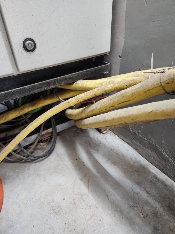
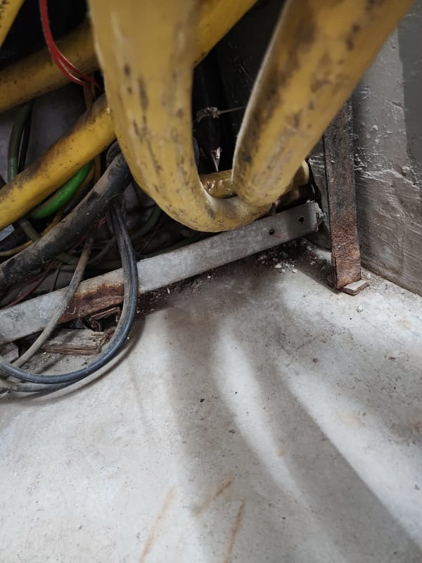
Photos attached of Cable entry - No Conduit used, only slight pass near to one of cable tray, and cable is unarmored
WhatsApp_Image_2023-09-02_at_11.21.03_nhzexd.jpg
WhatsApp_Image_2023-09-02_at_11.21.02_1_woph1n.jpg
WhatsApp_Image_2023-09-02_at_11.21.02_dwtatw.jpg
 
If that last photo is of the three cables, one of them doesn't look the same as the other two.

Also the overall quality of instalation looks very poor.

Remember - More details = better answers
Also: If you get a response it's polite to respond to it.
 
If that last photo is of the three cables, one of them doesn't look the same as the other two.

It seems so but it isnt. Meters are installed left middle and right, cable entry is same so farthest meter doesnt have any loops so seems shorter in length

Also the overall quality of instalation looks very poor.]
Agree but due to lesser space and unplanned expansion - and some frequent modification to counter this issues
 
Status
Not open for further replies.
Back
Top