Continue to Site

Eng-Tips is the largest engineering community on the Internet

Intelligent Work Forums for Engineering Professionals

  • Congratulations The Obturator on being selected by the Eng-Tips community for having the most helpful posts in the forums last week. Way to Go!

Parallel Cable Load Imbalance 2

Status
Not open for further replies.

7carisfast

Electrical
Jun 15, 2004
48
Ok guys, I really need your help on this one.

NEMA Size 7 500HP DOL Starter
Parallel 500MCM Cu Cables per Phase into contactor
Parallel 500MCM Cu Cables per Phase out of contactor
Length 75 Feet
Cable Tray Installation

Load Cables Measure 554 556 552

Here's where it gets wierd:

Independent Cables loads
242/312 253/303 308/244
 
Replies continue below

Recommended for you

7carisfast
This isn't very unusual or wierd. Your motor load is well balanced. Most likely what is causing the differential between cables of the same phase is differences in resistance in the terminations (at each end of the cable) between each cable of the same phase.

I am going to explain it with DC parlance although it is an AC system. The DC resistance of each of the 75' lengths is approximately .001935 ohms. It doesn't take much difference in termination resistance to be the major factor in the resistance of the cable system (cable and terminations). Since it must follow Ohm's Law (V=IR) and the voltage drop for each cable must be the same, the current in each cable adjusts to make the voltage drop (IR) in each cable the same.

Do you have crimp or mechanical lugs?
 
How, exactly, are the conductors run between the source and the contactor and between the contactor and the motor? What is the physical configuration? Are you sure it isn't 242/312 253/303 224/308? One side with lower reactance than the other side.
 
Hi.
Intresting case.
We had same phenomen several times. In all cases was same.
Parallel connection was not so parallel. Separate cable tray, other radius of inserting cables to cubicles, etc. in other words not same lenght.
75 feet is ( sorry, I must translate it to meter) about 23 meter. Check option: 242/312=58/75 or in meters 18/23. Not big difference.
I assume it's a "problem". As David wrote, check you physical configuration.
Ohm law is Ohm law.
Good luck.
Slava
 
davidbeach has a good point since the reactance affects the impedance (since it is an AC system). You should be triplexing your cables in the cable tray, which I assumed but maybe you don't do that. I have had the same current imbalance problem with conductors in rigid steel conduit and the conductors were all cut to the same length prior to pulling.
 
Thank you guys. The crimps are mechanical style and the installation in within cable tray with no particular structure of cable layout.

Gepman, I actual did neglect the cable resistance due to it's low value of resistance but then never thought of connection resistance imbalance. I have our facility taking a look at the physical connection as well. I'm wondering if they have the motor leads connected as lead-lead-feeder, feeder versus feeder, lead, lead, feeder. The first scenario would be more affected by any dirt or corrosion especially if the lower current conductor is on the "outer part" of the connection.

Thanks to all of you for your help. In any event, were ok with our cable ampacities, it was just freak'n wierd.
 
Hi 7carisfast,
I agree with all above possible explanations.
I think an imbalance may occur also when the two
cables of the same phase are in different magnetic
field created by all other parallel cables,as in
a cable tray the two cable are not in the same
position from the other cables.
I think that IEEE Power Delivery, IEEE Transactions on
Volume 6, Issue 2, Apr 1991 Page(s):479 - 487
[Buller formula] may be an other explanation.
"Calculation of current division in parallel
single-conductor powercables for
generating station applications"
regards
 
Hi,
I think post of 7another4 is right explanation. According to my small calculation, are possible serious problems in several cases.
Thank you.
Regards.
Slava.
PS
7carisfast
"In any event, were ok with our cable ampacities, it was just freak'n wierd."
I'm not shure.

 
I would be curious to see a cross section of the physical layout of the conductors. It would be nice if 7carisfast would make a sketch, scan it, and upload it to the site. He should also answer davidbeach's question if the one set of cable amperage measurements is reversed. I would also like to know the material and configuration of the cable tray.

Since the amperage splits between each phase pair is close to equal on all three phases I think that my previous explanation is NOT a good one since termination resistance usually is not that consistent when you are having problems. I think that you could check this with a very accurate volt meter (millivolt or microvolt) across the terminations and determine what percentage of the voltage drop is occurring across the terminations versus along the conductor. I haven't done this myself but I have used a micro-ohm meter to locate unintentional neutral to ground connections on busway.

The impedance (ohms per 100 feet) of 500 kcmil copper conductors in magnetic conduit is .00546 and in non-magnetic conduit it is .00458. .00458/.00546 is about 84% and I would expect this to be about the worst case of amperage split caused by a change in reactance due to one set of conductors being routed next to the edge of a steel cable tray. Curiously this is about the amperage split of conductors.

The reason proposed by 7anoter4 is an interesting one and I am inclined to go with it probably because I don't know how to calculate it! I rarely use cable tray but when I have I haven't noticed much difference in amperage in parallel installation than in conduit but I always require the single conductors to be triplexed together and this may help since they are with conductors of the other phases. Can 7anoter4 discuss or sketch the geometry covered in the paper (the abstract said it was six parallel conductors of the same phase) such as was it in a single layer, multiple layers, triplexed, non-metallic conduit, etc. and if the method is applicable to other geometries? If it is a single special geometry then I don't want to spend the $35 to buy the paper.
 
Did you measure the total load (meter around both cables) or just add your individual readings?
The difference is probably caused by unequal reactances of the cables. This is a result of cables run flat in a cable tray. The reactance of the cables depends on the position of the cables relative to each other.
A tight trefoil configuration will give better balance but less ampacity due to mutual heating.
It is not uncommon for the sum of the currents to exceed the total current. The voltage drops of cables with differing reactances will be at different phase angles. The result is a total current that is less than the sum of the parts.
Bad connections are not usually that equally bad. Looks more like reactance.
Enough resistance to cause that great a difference in current may result in noticeable heating at the location of the resistance.
respectfully
 
Hi.
Gepman, Waross your's explanation is eql. to 7another4, but in other word.see attached.

In one reported instance, a nominal total load of 2,300 amperes was being transmitted through three pairs of cable. One pair was found to be carrying 742 amperes, a second pair 441, and the third pair 550.

In another industrial plant, a circuit rated for 4,000 amperes was transmitting only 3,000 through paired cables installed as an emergency replacement for a failed bus duct. Soon after being energized, some of them became so hot they started smoking. To correct the problem, the individual phase conductors had to be bundled to balance their electrical positions , and the entire bundle then twisted through 3600 between the two ends of the circuit.

In 1996, an engineer reported even more extreme unbalance of four to one in currents through paralleled conductors of the same length. In his words: "That means of course, if you are counting on two 500 MCM conductors to carry 800 amperes, one may have 640 amperes on it while the other has only 160."

What the Code states

This is especially likely to occur in cable tray circuits, common in process industries. The National Electrical Code deals with the situation in Section 310.4, "Conductors in Parallel," mandating that each be of the same length, material, cross-sectional area, and insulation type, as well as being "terminated in the same manner." (This is most important for sizes 1/0 AWG and larger, intended for higher currents and consequently strong magnetic fields.)

In a "Fine Print Note," the Code also points out that "difference in inductive reactance and unequal division of current can be minimized by ... orientation of conductors." What the Code does not say (because it avoids answering "design" questions) is how proper orientation can be achieved. The basic principle is to make sure the flux linkages surrounding each parallel path will balance themselves out over the circuit length. These conditions should be met:

* If multiple raceways are needed, the same numbers of identical conductors must be contained within each one.

* The individual phase conductors should be grouped so that each occupies the same relative position in turn throughout the circuit length. In other words, "transposition" is necessary.

Regards.
Slava


Here's a link to some pictures of current distribution on a busbar with very basic geometry:
Three flat parallel conductors spaced one width apart. (Sorry, I don't know how to attach pictures directly.)

Please select the file SkinEffectInMultipleAndPolyphaseConductors.pdf

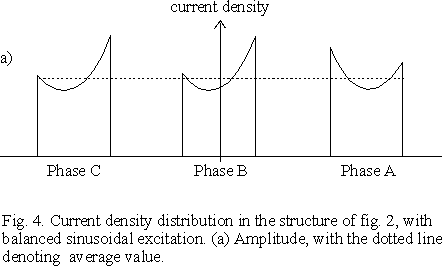
The picture 4a seems to explain also the question of reverse measurements by Davidbeach.

The picture is from article “Skin effect in multiple and polyphase conductors” by P. Silvester and was published March 1969 in IEEE transaction on power apparatus and systems. Page 231. (According P. Graneau the figure 4 makes history being the first of its kind.)

There is another article, “Finite element calculation of Eddy currents and skin effects” by John R. Bauer, in IEEE Transactions on magnetics, March 1982, page 504 , where the same busbar geometry has been calculated using finite element method (FEM).

My colleague used a Fortran program (FEM?) on late 70' to calculate current distribution and short circuit forces in three phase high current multiconnector busbars with various geometry. I wasn't involved but I remember that structure with a decently even current distribution was hard to find, because of skin effect and proximity effect.

Here's a small example of such multiconnector busbar and the ineven current distribution:

 
hi gepman,
If the IEEE Transactions is so expensive then :
"IMBALANCE CALCULATION ACCORDING TO EPRI-Power Plant Electrical ref. series"
VOL.4-WIRE AND CABLES
EQ.A-1 FROM APPENDIX A :
Ean=Ia1*(Ra1+jXa1)+Ia2(jXa1-a2)+Ib1(jXa1-b1)+...+Ia(Rl+jXl)
Ean = source phase A to neutral voltage
Ia1 = line current in conductor A1
Ra1 = conductor A1 ac res. at operating temp.
Xa1 =the self-reactance of conductor A1
Xa1-a2 the mutual reactance between conductor A1 and A2
Rl,Xl the load res. and react
Xa1=La1/1000*.023*[k+ln(1/rc)] La1= cond. A1 length[ft]
rc= cond. radius [inch]
k=.25 for concentric stranding
Xa1-a2=LA/1000*.023*ln(1/Da1-a2) LA= minimum of La1 and La2 or:
Xa1-a2=LA/10^7*4*pi*F*Ktrans*ln(1/Da1-a2) LA= minimum of La1 and La2 or:
Ktrans=measure unit/meter
Da1-a2= the distance betw. A1 and A2 conductors
nofd=no. of parallel cables per feeder
Iai*Zi-Iaj*Zj=[for k,l=1 to nofd] SUM(jIk*Xkj)-SUM(jIl*Xli)--k<>j,l<>i")
SUM(Iai)=Ia
May be useful.
Or for 2 parallel conductors per phase only, the F.Buller procedure [1949] may be employed.
I have only a qbasic algorithm for F.Buller iteration and I cannot interpret it now.
But is close to the Eq.A-1 from above.
regards
 
7carisfast,

Have you done an IR scan of the contactors? Over-tightened crimps reduce the area of the cable increasing the resistance, thus creating a hot-spot.
 
Runsor
I tried to access but it requested a password. Look at Step 3 in the reply box to see how to upload items to this forum.

I am also not certain how to interpret Figure 5 of The x axis is distance. Distance from what? What is the reference point?

The way I interpret the drawing there are six bars per phase. The top left of the "L" is one phase, the bottom right of the "L" is another phase, and the intersection of the "L" is a third phase. The drawing takes the three left bars of the intersection, rotates them 90 deg. counterclockwise and then this is the current distribution. The two areas with zero current density must be the spaces between the three bars. Apparently the bottom bar has the greatest current density although I don't intuitively see why since it looks almost equidistant from both of the other phases while the top bar is closer to the top phase than the right phase.

7anoter4
Thanks for the article citation. I will look for it. I have some contacts at EPRI.
 
gepman
I agree with your interpretation of figure 5 of Please note, that this busbar geometry has nothing to do with the original question about two parallel cables. This link is just the first example of proximity effect on current distribution I did manage to google.

There are six conductors for each three phases, but in figure 5 the current is shown for only the three leftmost conductors of the middle phase. The conductors are about 40 units wide and the gap is about 10 units. The current in the lowest conductor is about five times bigger than in the middle conductor and is in addition concentraced on the bottom edge of the conductor. This is because of the the mutual inductances with all the other 17 currents (proximity effect).
Neither is my intuitiveness enough to see all the needed geometric mean distances and matrix inversions or finite element method solution needed to solve the current distribution. :)

No password is needed (my colleague tested the link via an other ISP than mine) for

However, here's a second try. First the geometry of the busbar:
ProximityEffect2.GIF


and the current distribution
ProximityEffect4.GIF


This figure 4a does better correspond to the original question. There is only one conductor per phase, but the current distribution gives an idea how current would distribute if the conductors were splitted to two parts. The distribution is quite similar with the 7carisfast's original case. In any case, the position of the six individual motor cables and the cable tray are essential to the actual current distribution.
 
Hi.
I would like say many thanks to 7another4 and Runsor.
Your information was help us solve big problem.
Current distribution was same as in Fig 4.
Best Regards.
Slava
 
Status
Not open for further replies.

Part and Inventory Search

Sponsor