Continue to Site

Eng-Tips is the largest engineering community on the Internet

Intelligent Work Forums for Engineering Professionals

  • Congratulations KootK on being selected by the Eng-Tips community for having the most helpful posts in the forums last week. Way to Go!

Parallel cables on LV side of a transformer 1

Status
Not open for further replies.

PrebenJakobsen

Electrical
Dec 1, 2008
27
Hi Engineers
I have a 11/0.4kV 2500kVA trafo where I need 7 parallel single core cables to carry the current.
Ideal installation is 7 bunches of trefoil cables of equal length, installation conditions etc.
But the distance to LV swbd is only 5m and the phase sequence is opposite, so this requirement is very hard to fulfil.

I am therefore considering to have all L1 on one cable tray, L2 on another and L3 on a third.
In that way I am able to have almost same length of all cables, but the X value is out of control.
Is there any way to evaluate how the sharing between the 7 parallel cables of each phase will be?
Is it possible to look at the transformer + cable impedance to evaluate the sharing?

What would you prefer
- 21 cables of same length but with all L1 on one tray, L2 on another and L3 on a third
- 21 cables in 7 times trefoil but with a length variation of 30% or more

PS: When phase location is solved I will ask about the neutral.
PPS: I would like to avoid modifying the equipment to accommodate a busbar system

Best Regards
Preben Jakobsen

 
Replies continue below

Recommended for you

Hi Preben,

First: Are you sure 7 bunches are enough? Are you sizing them under NEC or IEC? Tt seems that you are falling short... Are you using correction factors based on circuit grouping?

Second: I think is better to have different lengths but place them in trefoil, not only you "control" the reactance but also you cancel magnetic field between phases

Regards.

JBC
.......
"The more I read, the more I acquire, the more certain I am that I know nothing"
 
Think very hard about a bus solution.
Have you derated the cables due to the mutual heating effect?
I have more than once had to correct problems due to the original installation being a phase conductors being together , "B" phase conductors being together and "C" phase conductors being together.
The correction consisted of arranging the cables in "A", "B", "C" groups.
I have always considered 10% to be the extreme limit for differences in length between parallel cables. I have never gone to that extreme. 1% or 2% difference in length, max.
Think again about a bus solution.

Bill
--------------------
"Why not the best?"
Jimmy Carter
 
The shorter the length, the more impact cable length differences will have on shared current. I would be concerned. Bill's suggestion is good - a short run of bus might solve the problem.
 
Thanks for the replies.
If I should start over I would use a busbar system, but now I am stuck with cables.
I am on an IEC system and might need 8 cables depending on parameters used.

My basic problem is the current sharing.
I have seen more installations where the cables are in flat formation and there is clearly quite a big length difference.
But I can't find anyone who have actually measured how the current distribution is.

Has anyone tried to make calculation supporting the 10% rule of thumb?
Has anyone tried to make parallel cables of unequal length and measure current distribution afterwards?

Best Regards
Preben
 
The problem with a linear solution is that the impedance of the cable portion responsible for the different length may not be linear with respect to the main portion of the cable.
In many locations you may need the AHJ to sign off on an unbalance of more than 1% or 2%.
Before I went to the AHJ with a 10% unbalance I would derate the cables by about 15%.

Bill
--------------------
"Why not the best?"
Jimmy Carter
 
Unconventional problems often demand unconventional solutions.
Is it possible to swap the primaries to change the phase rotation of the secondaries?
Will that help?
Is there any other way to change the phase rotation?

Bill
--------------------
"Why not the best?"
Jimmy Carter
 
It is important that all of the conductors of a given phase be approximately the same length; it is not nearly that important that each of the phases have the same length.

If you have 8 conductors that start with one of a given length and each additional is 2% longer than the one before it, the last one carries only 87% of the current of the first one. Make it 5% steps and the longest one only carries 71% as much of the current as the shortest one.

If seven or eight equally loaded conductors can carry the load, it may take 10 or 12 conductors of differing lengths to keep the shortest one from overloading.
 
Howdy PJ,
Is it common (for where you work) to use cable-bus?
That would always be my first choice for any xfmr secondary feeder (here in N.A.).
I recommend MPHusky as a preferred OEM for cable-bus(again here in N.A.).
GG


"I have not failed. I've just found 10,000 ways that won't work." Thomas Alva Edison (1847-1931)
 
For the distance you are talking about, the length difference owed to trefoil v. stacked would probably be insignificant. However, I'd stack em as you suggest (L1 on one tray, L2 on another, etc), space em at least one conductor diameter apart, and derate as needed. I have done the same and even stacked the cable trays over/under to save room.

 
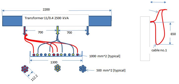
I would use only 4 cables/phase of 1000 mm^2 copper. It is important to put the cables in certain order in order to reduce the current unbalance[see the attached link]
In my opinion run the cables in a formation 1 in center and 7 in an outside circle at distance more than 5-6 times the cable bunch diameter could reduce the current unbalance between parallel cables per phase.
7_single_core_per_phase_f19emo.jpg
 
Status
Not open for further replies.

Part and Inventory Search

Sponsor