Continue to Site

Eng-Tips is the largest engineering community on the Internet

Intelligent Work Forums for Engineering Professionals

  • Congratulations KootK on being selected by the Eng-Tips community for having the most helpful posts in the forums last week. Way to Go!

Parallel, Position or Envelope? 2

Status
Not open for further replies.

TopPock

Mechanical
Jan 10, 2023
1
Hi,

I've been trying to correctly define a feature that feels like it should be simple but keeps being inspected wrong so I figure I'm probably speccing it incorrectly.

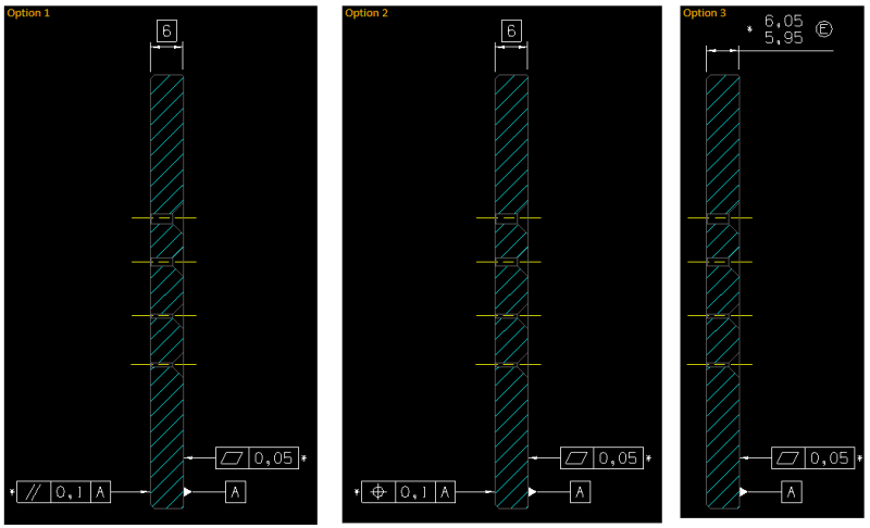
Have a look at this image:
para_pos_or_env_oj0fzx.png


I want the face on the left to be restrained to datum A by the shown tolerance.
I've currently got it as a parallelism as this intuitively makes sense. However I'm beginning to think parallelism can't be used with a TED so I created option 2 that uses position. However this use of position has confused inspectors in the past. Then I realised I had my head up my ASME and had been assuming the envelope principle applied, when I actually follow ISO. So I created option 3 and stuck an E on it.

Are any of these correct (to ISO)?

As for inspecting it I was thinking a granite table and a height gauge would do the job. But then I'm not sure how this would be recorded/reported... for feasibility I'd want to know the height of a bunch of points to understand how the part is distorted but when it moves into routine inspect I guess I just want to know the minimum and maximum height?
Currently I'm just getting a single width (6mm) dimension and a parallelism which apparently was inspected using a micrometer... hmmm.

Thanks in advance!
 
Replies continue below

Recommended for you

Option 1: the left face is not located to the right feature (datum feature A). Parallelism cannot locate features. It can just orient them. Therefore, option 1 is an incomplete drawing.
Options 2 and 3: look complete to me, however I am not sure they will have the same mathematical results. Most likely they don't.

 
TopPock,

It's interesting how we often have significant GD&T problems with features that seem very simple. Features of size such as widths and cylinders are notorious for this.

Option 1
-This is correct as per ISO, but incomplete
-I would agree that the 6 mm TED does not apply to the parallelism tolerance.
-Nothing is controlling the thickness of the feature.
-To inspect the parallelism tolerance, the datum feature a face would be laid on the surface plate and the height of the upper surface measured relative to the plate. All of the height measurements would need to be within a range of 0.1

Option 2
-This is correct as per ISO - position can be used to control the location of a planar surface relative to a planar datum feature (and is equivalent to surface profile in this case).
-I also agree that this will confuse inspectors who are used to ASME, which does not allow position to be used in this way.
-To inspect the position tolerance, the datum feature A face could be laid on the surface plate and the height of the upper surface measured relative to the plate. All of the height measurements would need to be between 5.95 and 6.05.

Option 3
-This is also correct per ISO.
-The width tolerances requires that the "local sizes" are all between 5.95 and 6.05. These are 2-point distances, measured normal to the median plane of the feature. Local size cannot be measured properly by measuring the height from a surface plate (a micrometer-type device is best).
-The (E) envelope requirement requires that the entire feature (both surfaces) fits between two parallel planes 6.05 mm apart. This could be checked (approximately) by laying one side down on the surface plate and measuring the height relative to the plate. All of the height measurements would need to be 6.05 or less.

So the inspection methods need to reflect these definitions, and it sounds like that is currently not the case. Parallelism (or flatness) definitely cannot be measured with a micrometer.

One question - on this part, is there any way to distinguish which side is datum feature A (and thus needs to be flat within 0.005) ?

Evan Janeshewski

Axymetrix Quality Engineering Inc.
 
Evan,
The holes are the features that would allow to distinguish which side is datum feature A, as the countersinks are not symmetrical.

TopPock,
I agree with greenimi and axym that all options are legal as per ISO and that option 1 is incomplete. If I understand your description correctly, option 2 is the closest to what you want to accomplish. It is not a sin in ISO to use profile of a surface instead of position in cases like this (if position looks confusing).

greenimi,
The mathematical/geometrical difference between options 2 and 3 is that as per option 3 the local thickness of the part can never be less than 5.95, whereas as per option 2 it can go down to 5.90.
 
pmarc said:
The mathematical/geometrical difference between options 2 and 3 is that as per option 3 the local thickness of the part can never be less than 5.95, whereas as per option 2 it can go down to 5.90.

Thank you pmarc for the detailed explanation. I knew It is something different, but I was not sure exactly what.


pmarc said:
The holes are the features that would allow to distinguish which side is datum feature A, as the countersinks are not symmetrical.
I don't know how OP's part work and its design intent, but just using my logic (how much I still have left) seems to me that datum feature A should be the opposite side of the countersinks, doesn't it?
If the countersank screws are used, then I would say the opposite side would make a full contact and its acting as primary datum feature (and not the same side where the c'sink features are present).

What do you think?

 
Thanks for you detailed and knowledgeable replies, this has really helped. (I'm TopPock btw, different account due to issues)

Good to know I'm not way off the mark and there is just lots of ways to slice it.

Those countersunk holes are actually there to act as a lead in for some tubing. The part is assembled with datum A screwed against another component. Although it's not the entire face so maybe I should make the datum feature only a section of face at risk of over complicating it.

I don't really care about local thickness, it's the distance from the mating part that matters which is why I prefer option 2 as it conserves the relation to the datum. That being said, if the thickness did vary then upon tightening, the plate could be pulled flat bringing the distance from datum A to the face out of spec. Though I guess the flatness constraint limits the extent to which that could happen.

To be honest it needs a design change but my hands are tied so I just need to get it through DV.
 
If local size isn't important, you could add Tangential modifier.
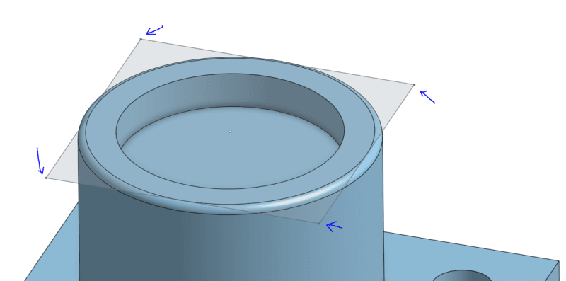
BUT, if this is disk shaped, then check what CMM software is doing first.
It can be problematic if evaluates one of the corners blindly:
virt-plane65_vodiq8.png
 
cr7 said:
If local size isn't important, you could add Tangential modifier.

How the tangent plane modifier is to be used in this case? I am not very familiar with ISO's tangential modifier.
 
greenimi,

The tangent plane modifier would be specified same as in ASME. The modifier would appear right after the tolerance value in the tolerance frame.

In ISO GPS, in case of nominally planar features, there are two more modifiers to consider:
- (G) - the least-squares associated plane without material constraint to be evaluated.
- (C) - the min-max (Chebyshev) associated plane without material constraint to be evaluated.
 
Thank you pmarc for your pertinent and detailed answer. I appreciate your help in my (continuous) education regarding standards.
 
Status
Not open for further replies.

Part and Inventory Search

Sponsor