TopPock
Mechanical
- Jan 10, 2023
- 1
Hi,
I've been trying to correctly define a feature that feels like it should be simple but keeps being inspected wrong so I figure I'm probably speccing it incorrectly.
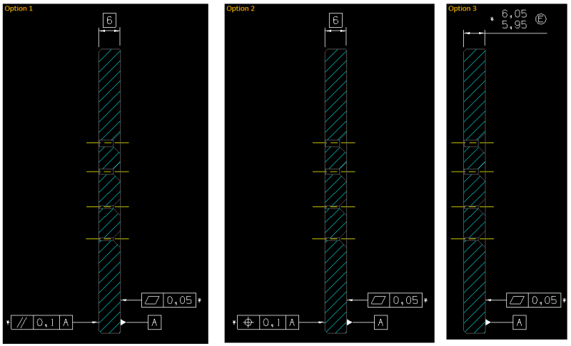
Have a look at this image:

I want the face on the left to be restrained to datum A by the shown tolerance.
I've currently got it as a parallelism as this intuitively makes sense. However I'm beginning to think parallelism can't be used with a TED so I created option 2 that uses position. However this use of position has confused inspectors in the past. Then I realised I had my head up my ASME and had been assuming the envelope principle applied, when I actually follow ISO. So I created option 3 and stuck an E on it.
Are any of these correct (to ISO)?
As for inspecting it I was thinking a granite table and a height gauge would do the job. But then I'm not sure how this would be recorded/reported... for feasibility I'd want to know the height of a bunch of points to understand how the part is distorted but when it moves into routine inspect I guess I just want to know the minimum and maximum height?
Currently I'm just getting a single width (6mm) dimension and a parallelism which apparently was inspected using a micrometer... hmmm.
Thanks in advance!
I've been trying to correctly define a feature that feels like it should be simple but keeps being inspected wrong so I figure I'm probably speccing it incorrectly.
Have a look at this image:

I want the face on the left to be restrained to datum A by the shown tolerance.
I've currently got it as a parallelism as this intuitively makes sense. However I'm beginning to think parallelism can't be used with a TED so I created option 2 that uses position. However this use of position has confused inspectors in the past. Then I realised I had my head up my ASME and had been assuming the envelope principle applied, when I actually follow ISO. So I created option 3 and stuck an E on it.
Are any of these correct (to ISO)?
As for inspecting it I was thinking a granite table and a height gauge would do the job. But then I'm not sure how this would be recorded/reported... for feasibility I'd want to know the height of a bunch of points to understand how the part is distorted but when it moves into routine inspect I guess I just want to know the minimum and maximum height?
Currently I'm just getting a single width (6mm) dimension and a parallelism which apparently was inspected using a micrometer... hmmm.
Thanks in advance!

