Continue to Site

Eng-Tips is the largest engineering community on the Internet

Intelligent Work Forums for Engineering Professionals

  • Congratulations KootK on being selected by the Eng-Tips community for having the most helpful posts in the forums last week. Way to Go!

Parallelism

Status
Not open for further replies.

Kedu

Mechanical
May 9, 2017
193
NT1_-_Copy_dnoc0h.jpg


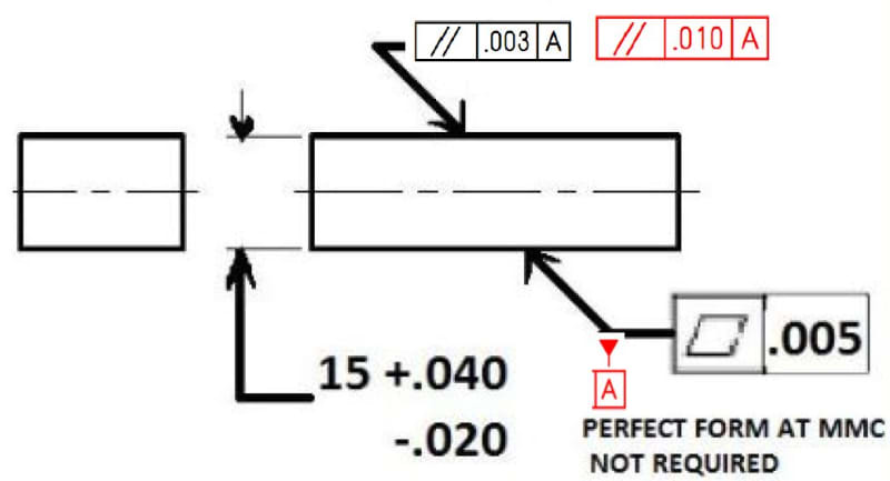
For the part shown use ASME Y14.5-2009 and determine what would be the maximum envelope for this part?

Will the parallelism of 0.003 (black option) versus 0.010 (red option) make any difference in calculation the maximum envelope?
(datum feature A is the same for both options = the bottom surface controlled with flatness within 0.005)
 
Replies continue below

Recommended for you

drawoh,

I don't think anyone said its a good idea, but its certainly "allowed". One could take it to the extreme case where the flatness tolerance on the bottom surface (datum feature) is an order of magnitude larger (say 0.01 or 0.1) than the parallelism tolerance on the top surface. In this case the "rocking" of the datum feature would be so extreme that all but a tiny subset of orientations/candidate datums would reject the part. This is obviously a terrible idea but the standard does not forbid it.
 
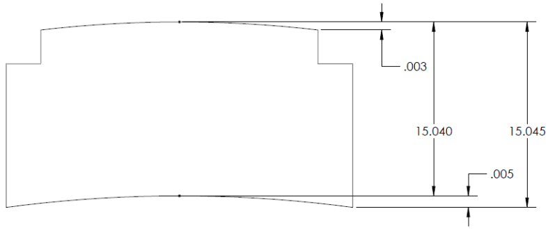
Isn't the length of the right edge = 15.040 - .003 + .005 = 15.042 greater than the allowable 15.040?
 
3DDave, you are absolutely correct. Thats what comes of trying to exaggerate the scale as I had to override the dimensions on the model to show them properly. I have to revise my previous statement - it seems the tightest form tolerance on either side would limit the maximum envelope. In this case it would be 15.043, thank you for pointing that out.
 
pylfrm,

I agree with the others that there is no as-produced part with an AME of 15.045 that meets the 0.003 parallelism and 0.005 flatness tolerances. You hinted at this in an earlier post, and I see that you were correct. I had initially thought that a curved part that was thick in the middle would meet this criteria but I didn't fully think it through. Once I tried to sketch an actual part, I saw that this didn't work.

Evan Janeshewski

Axymetrix Quality Engineering Inc.
 
3DDave said:
Isn't the length of the right edge = 15.040 - .003 + .005 = 15.042 greater than the allowable 15.040?

Look carefully at my OKAY view above. Also, look at ASME Y14.5-2009 Figures 2.7 and 2.8. I have correctly oriented the 15[ ]dimension arrows. The maximum height is 15.045. Ordinarily, this would be prevented by Rule[ ]#1.

HEIGHT = .005 + 15.040 = 15.045.

The .003 flatness is irrelevant.
 
chez311,

Your proposal should work with a slight modification:

FLATNESS_ofjhxt_modified_as7hqw.png


This scheme can be used in either direction, so it should allow a UAME size of (15.040 + max(flatness, parallelism)). A different scheme would probably allow a UAME size of (15.040 + flatness + parallelism).

I realize this may violate the intent of OP's question.


pylfrm
 
Pylfrm said:
I am curious: Why do you ask this question? If the UAME size is relevant, why wouldn't it be controlled more directly?

Pylfrm,
Was an application discussed at work in a meeting with a supplier and our engineer wanted to give as much tolerance as he thinks he can give and make the supplier happy (he got away with as much as possible).
Canceling rule 1 was an easy decision, but adding some form controls based on the supplier capabilities was not so much hence the questions.
 
pylfrm,

Thats an interesting point - the faces on either side could also be tapered significantly either by design or if there is no (or extremely loose) orientation/size control on them. The step you show would of course have to be included in the design (though I doubt the impact on function would be acceptable in most cases) - the solution otherwise would be to have equal form control tolerances on the datum feature and controlled surface opposite to it in order to be able to use the full tolerance. This is obviously not an ideal situation for most cases for the reasons mentioned in above posts, and additionally if the datum feature were convex (ie: it rocks) and the opposite side used up the entire tolerance zone there could possibly be only a single orientation under which the part would pass inspection. This would likely not coincide with the "single solution" orientation mandated by the 2018 standard on a real part.

The irony of the exercise is that even if both surfaces were given the same amount of tolerance, most shops (or at least most competent shops) would likely produce the datum feature to a sufficiently higher level of accuracy to prevent such issues.
 
Pylfrm said:
This scheme can be used in either direction, so it should allow a UAME size of (15.040 + max(flatness, parallelism)). A different scheme would probably allow a UAME size of (15.040 + flatness + parallelism

Pylfrm,

Could you explain a little bit in more details in which case would you use the max between flatness and parallelism and in which case would you use the sum of flatness and parallelism ?

I am unclear how the part would look like in those 2 cases added by you.
 
Status
Not open for further replies.

Part and Inventory Search

Sponsor