Continue to Site

Eng-Tips is the largest engineering community on the Internet

Intelligent Work Forums for Engineering Professionals

  • Congratulations Toost on being selected by the Eng-Tips community for having the most helpful posts in the forums last week. Way to Go!

Parellelism Against A Complex Surface

Status
Not open for further replies.

brwalker145

Mechanical
Jun 13, 2023
7
Hello all, long time reader, first time poster...

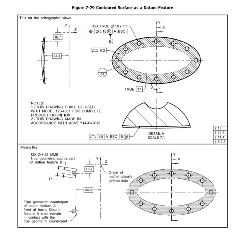
I have a customer-supplied print that calls out a Parallelism inspection against Datum D. However, the feature they have defined as Datum D is a non-planar complex surface (it looks flat on the print, but it's not). I have been arguing that we cannot measure Parallelism as currently defined, but the customer insists that the print is correct.

Am I wrong here? I just don't see how this could possibly be measured. I'll be the first to admit that I am far from a GD&T expert, but unless I've completely missed it, I don't see anything in Y14.5-2018 that would support their argument.
 
 https://files.engineering.com/getfile.aspx?folder=a91c0203-7365-4a45-9724-03afa3fa0ca5&file=Parallelism_Example.JPG
Replies continue below

Recommended for you

If the problem is establishing a datum plane based on the non-planar surface, It is generally possible. But the relationship between the datum reference frame and the complex datum feature has to be fully defined, and the datum feature should be referenced as BSC (basic). See the below example from ASME Y14.5-2018 (datum feature A).
Screenshot_20230613_194817_Drive_hwxz41.jpg
 
Is the [5.75] all-around reference showing how far the tangent of the raised part is from [D]?

If that raised surface isn't nominally flat then parallelism isn't correct. It will likely require some note to indicate that the profile is to be uniform within the desired tolerance as measured at each normal section to the raised lip.
 
We might not know how this part works and functions in the overall assembly, but I am just tossing it out there: the tangent plane modifier T could be an option to be used in the parallelism callout.
 
Burunduk,

Thank you for the info/reference, I think this supports my argument that parallelism cannot be measured as currently defined on the print, as there isn't a defined plane for the feature to be parallel to; am I interpreting that correctly?


3DDave,

That's another odd one I've asked the customer for clarification on. The [5.75] is a distance from the raised feature (i.e. rib), to an inflection point on D's surface. However, the geometry/inflection is not continuous for an "all-around" designation to [edit: make] sense. I understand their intent, as the overall distance between the rib and surface D is critical for the secondary processes, but I don't agree that's the correct way to go about it.


Greenimi,

Surface D is contacted during the secondary process (sonic welding) with a contoured form/nest. As I mentioned above for 3DDave, that overall height is critical for the secondary process to ensure a consistent weld. Based on the geometry of the surface, I'm not sure that a tangency modifier would accomplish what they need, but I appreciate the suggestion.
 
OP said:
.....overall height is critical for the secondary process to ensure a consistent weld....

If that is the case and the overall height is critical, then why are you using the parallelism callout?
 
No idea. This is a customer-supplied print, so that's a question for their quality group. For other similar parts, there's typically a direct measurement of the rib/energy director height.
 
OP said:
No idea. This is a customer-supplied print, so that's a question for their quality group. For other similar parts, there's typically a direct measurement of the rib/energy director height

OP said:
overall height is critical for the secondary process to ensure a consistent weld.

So, my point is: the overall height could be critical for your process, but not neccessary critical for the function of the part. And the drawing reflects (or should reflect) the design intent, regardless of the process and regardless if you can measure the requirement or not.

 
greenimi said:
regardless of the process and regardless if you can measure the requirement or not.

I'm not sure I understand: If a requirement cannot be measured as defined, why would it be on the drawing in the first place?

My obligation as the supplier is to provide finished goods that meet all specifications outlined on the print; if something cannot be measured, it needs to be removed or modified. Ultimately it's the customer's responsibility to ensure the defined inspection criteria are valid and control the features necessary to ensure fit/function.
 
OP said:
My obligation as the supplier is to provide finished goods that meet all specifications outlined on the print; if something cannot be measured, it needs to be removed or modified. Ultimately it's the customer's responsibility to ensure the defined inspection criteria are valid and control the features necessary to ensure fit/function.

Well, I totally disagree with you assessment, specially with "if something cannot be measured, it needs to be removed or modified"
Don't let the tail wag the dog, meaning the inspection to drive the product definition.
 
Conveniecnce for measurement?
Sorry this argument is not good enough as you are not defining your print by a convenience for measurement. The driving force is the function not the measurement/ quality.
 
I'm not talking about removing/modifying "hard" measurements for sake of convenience, I'm referencing items that I physically cannot measure as defined, e.g. the parallelism call-out that this thread is about. In those instances, the print needs to be updated to either fix the incorrect call-out, or remove the spec if there's no value added.


p.s. I hope I'm not coming off as combative, I appreciate your input.
 
OP said:
I'm referencing items that I physically cannot measure as defined,

This argument is older than the like. LIFE. It is a chicken and the egg type of arguments.
Just because you ("the supplier") cannot measure it that does not mean it is not a functional requirement. Sometime you don't have to measure it. You can qualify it based on your existing process/ tooling.

So, I don't agree with your statements (again, even if appears to be conflictual). I am doubling down.
What seams to be missing from your original picture attached is that the surface circled in red is not located to the datum D. It is only oriented to it.
So, if parallelism is changed to profile (and then maybe refined with parallelism---with or without tangent plane T modifier) could be a more complete / better defined drawing.
 
I think we're arguing in circles over two different things, so let me ask this:

1. Is the measurement valid? (I.e. can it be measured as currently defined on the print?)

2. If valid, what is the physical setup to measure it?
 
brwalker145 said:
I think this supports my argument that parallelism cannot be measured as currently defined on the print, as there isn't a defined plane for the feature to be parallel to; am I interpreting that correctly?
Yes you are.
 
Feature shown with datum feature D symbol (and profile callout) does not have any basic radius therefore I interpreted as a nominally flat feature. Again, I am not talking about the "as produced" feature, but as designed feature. As produced feature could be "bow" within 0.4.

And then, at least at this point in time, the parallelism callout looks legit.
If more evidence is presented I will stand corrected.

 
brwalker145,

I answered your questions above, now, could you, please asnwer answer mine:

If parallelism (0.1 wrt D) is changed to profile (with or without tangent plane T modifier) could you now measure it?

 
If possible, walk away from this work; no-bid, whatever it takes.

This is a tarpit part.

The callouts shown make no sense. They apparently have dug in and said they know what they want. If you (your company) requests them to demonstrate they will feel sure you (your company) is the problem. Only if you are very lucky can you get the person responsible for this to explain what it is they were intending to achieve and how they believe they can achieve it.
 
3DDave,

3DDave said:
They apparently have dug in and said they know what they want. If you (your company) requests them to demonstrate they will feel sure you (your company) is the problem. Only if you are very lucky can you get the person responsible for this to explain what it is they were intending to achieve and how they believe they can achieve it.


Probably we should advise the OP on the technical staff and leave the commerical aspect for the more intelligent and well informed folks.

3DDave said:
If possible, walk away from this work; no-bid, whatever it takes
Fearmongering does not help anyone.
 
I interpreted as a nominally flat feature
If more evidence is presented I will stand corrected.

Initial post:
the feature they have defined as Datum D is a non-planar complex surface (it looks flat on the print, but it's not)

Probably we should advise the OP on the technical staff

I did, based on what was presented and not on some alternate misreading that isn't the presented case.

If the engineer responsible for the drawing shows up then a different examination can be done, but in this case where the OP is unable to make any changes to the drawing or make any evaluation of what would be an appropriate change to make, there is only one decision - Can this scheme yield a useful interpretation? That answer is "No." So what is a supplier supposed to do with a part they cannot properly inspect?

The clue to the situation is in the original problem statement:

the customer insists that the print is correct.

Perhaps we can get greenimi on a flight to explain to the customer that the situation is made much simpler if datum feature D is perfectly flat and not the geometry the customer currently has in mind.

Until then the OP underlying problem isn't the drawing, it's the failed relationship with the customer and their insistence this is correct.
 
Status
Not open for further replies.

Part and Inventory Search

Sponsor