Continue to Site

Eng-Tips is the largest engineering community on the Internet

Intelligent Work Forums for Engineering Professionals

  • Congratulations cowski on being selected by the Eng-Tips community for having the most helpful posts in the forums last week. Way to Go!

Part II - Column 3D Interaction Surface vs Code Biaxial Formulae 4

Status
Not open for further replies.

Trenno

Structural
Feb 5, 2014
831
thread507-460377

What are people's opinions on applying 3D interaction diagrams or codified biaxial for walls?

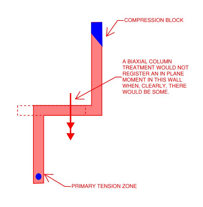
I'm thinking factors like high aspect ratios, return walls and end bar clusters would skew the results compared to a stocky square column. Essentially the buckling mechanism would be different a "wall" and a "column." 2D element v 1D element.


Replies continue below

Recommended for you

admittedly all my design work revolves around SDC A or B structures so my practical, and really general for that matter, knowledge around moderate to high seismicity detailing is almost none.

KootK said:
..directing us to use the same strain compatibility assumptions that we are directed to use for beam-column elements of any strife..
yeah this was my point, there is nothing in ACI that limits or suggests the strain compatibility approach is limited to uniaxial bending applications.

KootK said:
When a shear wall rocks up onto it's compression zone, we're basically saying that that compression zone forms a chunk of wall over which the full compression strength of the wall is mobilized.
Ok but how does a biaxial approach really differ from a uniaxial approach in this regard?
In the example in your next post, if you looked at each segment in "strong" axis bending only you'd have maybe deeper compression blocks resulting is heavier loaded compression regions. The biaxial analysis gave you a smaller area in compression so less compression demand. When you start factoring things like diaphragm torsion in to a segmented "strong" axis only approach now your talking compression hotspots all over the core which rely heavily on the flexibility produced by the segmented approach which in my mind would have a very different plastic hinge mechanism than the biaxial sketch which my not be realized before you've failed the likely more rigid biaxial core. As with all of this though it likely comes down to the details, to get the biaxial core behavior stresses need to be able to resolve around all of the turns in the section.

KootK said:
.., treating that strip as one would a non-shear wall under uniform compression isn't going to work.
Wasn't really suggesting this, a wall is always going to have a stress gradient across it's length and even thickness really. From what I can gather it seems most the major software players are turning this gradient into a P and an M applied at the wall center then performing the cross section ultimate analysis or taking the shell approach and doing strip designs and integrating the gradient.

KootK said:
...are intended to address uniaxial, strong axis flexure.
Ok, but what is the strong axis?
For an L section reinforced like a beam the compression block is just in the upper corner opposite the flange.
For the pre-cast stadium riser the strong axis produces a compression block split over the various flanges, does that little triangular compression region on the far right in the image in my previous post not have the same buckling potential.

There are a lot of instances where the strong axis is well weird.

KootK said:
..that a seismic shear wall is predominately a beam, by definition,..
Didn't you just argue in your above points that this isn't the case? Or is this a distinction between a Shear Wall vs a Gravity Wall?

My Personal Open Source Structural Applications:

Open Source Structural GitHub Group:
 
Celt83 said:
admittedly all my design work revolves around SDC A or B structures so my practical, and really general for that matter, knowledge around moderate to high seismicity detailing is almost none.

Pretty much everything that I wrote should apply to wind as well as seismic. With wind, you're still effectively executing a beam design in which you're telling the story of a wall that cracks, lifts off in the tension zone to engage the vertical reinforcement, and pounds all of the compression into the zone of concrete that you have designated as being part of the compression block. Seismic's only worse because it's more cyclical and more inelastic.

Celt83 said:
yeah this was my point, there is nothing in ACI that limits or suggests the strain compatibility approach is limited to uniaxial bending applications.

I agree, there is nothing in ACI that limits the strain compatibility approach to being used in uniaxial wall bending applications. My point is that there is also nothing in ACI that explicitly suggests that the strain compatibility approach, unmodified, is an appropriate tool to capture the behavior of a complex wall assembly like the one that I posted previously. And, given all of the design complexities that I would expect to accompany such a complex situation, I would have expected such an explicit endorsement if that was ACI's intent. The [hu/16] business is really a tacit acknowledgement that walls are, in some respect, not just columns.

Celt83 said:
Ok but how does a biaxial approach really differ from a uniaxial approach in this regard?

Frankly, I don't know. It seems to me that it's kind of a theoretical no-man's land. I do have some theories though:

1) What does tension lag look like when the shear path connecting the chords is a circuitous, accordion web thing rather than solid concrete?

2) Unlike columns, it's tough to load a wall assembly flexurally without inducing torsion in it. What does torsion resistance look like in a wall assembly that's already developed a flexural hinge? Or do the diaphragms iron all of that out in multi-core floor plans?

3) As the shear struts in the corrugated webs are forced to turn all of those corners, will conventional wall detailing there keep those abutting struts from blowing out from the wall? This is an issue even with simple I-shaped walls under seismic load.

4) As you know better than most, even the basic Whitney stress block is not really applicable to triangular compression blocks. Do we really think that we have something suitable for the compression blocks that might arise in these complex wall assemblies where you might actually have multiple, separate compression blocks?

...I could probably go on all afternoon.

Celt83 said:
When you start factoring things like diaphragm torsion in to a segmented "strong" axis only approach now your talking compression hotspots all over the core which rely heavily on the flexibility produced by the segmented approach which in my mind would have a very different plastic hinge mechanism than the biaxial sketch which my not be realized before you've failed the likely more rigid biaxial core.

To clarify, I am not suggesting that wall assemblies be treated as individual walls. Rather, what I'm saying is this:

5) It is my opinion that, to date, ACI has been largely silent on how complex shear wall assemblies ought to be designed.

6) I don't feel that a few passing ACI references to conventional strain compatibility makes this settled dogma. I feel that we've much left to discover and that the conversation should continue here, in practice, and in academia.

Celt said:
Wasn't really suggesting this.

You referenced 14.4 and the moment magnification procedure which, in my mind, are built for out of plane wall design. The procedure can certainly accommodate a gradient in axial compression along the length of a wall but not so much of a gradient that the entire width of the wall would lift off, as is the case with shear wall design. The point that I was trying to make with this bit is that the out of plane wall design procedures really do not play well with the in plane wall design procedures. As such, I don't believe that ACI's direction on out of plane wall design should be taken to also serve as definitive direction for in plane wall design.

Celt83 said:
Ok, but what is the strong axis?

KootK said:
...are intended to address uniaxial, strong axis flexure in linear, non-compound, single wall elements.

Celt83 said:
Didn't you just argue in your above points that this isn't the case? Or is this a distinction between a Shear Wall vs a Gravity Wall?

I've been speaking to shear wall situations and, I believe, consistently considering them to be beam-column members generally skewed pretty heavily towards the beam function. My point was that a shear wall only needs tension reinforcing if the eccentricity of its axial load lies beyond the extend of the wall. So, clearly, most practical shear walls will have load eccentricities grossly in excess of the minimum values that we apply to columns.
 
Excuse the sidebar, just a lightweight trying to keep up here:

In the previous discussion,
KootK said:
.., treating that strip as one would a non-shear wall under uniform compression isn't going to work.
Celt said:
Wasn't really suggesting this, a wall is always going to have a stress gradient across it's length and even thickness really.

Are we saying that a strip representation (of a boundary element to a simplify the 3D problem back to combined axial and bending) is:

A) inappropriate (overly simple) because it doesn't capture the effect of the stress gradient within our arbitrary/finite strip length (leading to buckling at an extreme fiber)

B) or that it is inappropriate (conservatively?) because of the effects on our finite strip from the remaining section

----
just call me Lo.
 
I’m on edge of the rabbit hole with some technical papers.

On some quick skims of about 8 papers buckling of the compression reinforcement seems to be a common failure method. Again on some quick skims this failure may or may not occur below the section capacity determined by a biaxial strain compatibility analysis, however a lot of the papers don’t appear to even consider the strain-compact approach and just jump right to test specimens.

I’ll post a list of the documents I found so far tomorrow.

My Personal Open Source Structural Applications:

Open Source Structural GitHub Group:
 
lomarandil said:
A) inappropriate (overly simple) because it doesn't capture the effect of the stress gradient within our arbitrary/finite strip length (leading to buckling at an extreme fiber)

1) Not inappropriate per se but, rather, difficult to make work given that the strip representing a shear wall compression block will essentially be designed to its squash load.

2) While I don't see anything wrong with designing the compression block using a strip approach, I've also never known anyone to do it that way.

lomarandil said:
B) or that it is inappropriate (conservatively?) because of the effects on our finite strip from the remaining section

I do think that would be a conservative approach for a shear wall compression zone which will benefit from being forced to move in concert with neighboring sections of wall that are compressed less or not at all. That said, as I mentioned at the top, I do personally like the idea of designing wall chords as stand alone columns for the direction perpendicular to the wall. I've always felt the [hu/16] criterion a little non-rigorous compared to how we evaluate other compression members.
 
1) The sketch below shows another, interesting area of concern for me. A classic column design approach wouldn't pick up the in plane moment in that central wall segment.

2) An appropriate ETABS model would pick up the in plane moment in the central wall segment.

3) In many buildings, this moment would be restrained by the diaphragms and transferred to other lateral elements within the building. However:

a) this path has meaningful flexibility associated with it which will reduce the efficiency with which shear is transferred between the tension reinforcing and the compression block. In conventional column design, this shear transfer mechanism is assumed to be infinite.

b) this approach requires one to design all of the lateral elements in concert rather than designing one at a time in isolation.

4) Through the course of this discussion, I've come to realize that, for me, there are two distinct classifications of shear wall:

a) Walls for which the shear web is a single, planar wall regardless of the presence of flange walls. Most of the compound wall research is geared towards this kind of wall.

b) Walls for which the shear web is comprised of multiple segments that are not co-planar. Accordion webs. This condition concerns me much more and has been studied much less.


C01_mtvakn.jpg
 
How would a strain compatibility approach not register an in plane moment in that section, assuming there is reinforcement distributed across the area?
As long as that area has bars, if you pulled that section out in isolation the variation in reinforcement strains and in turn forces would absolutely yield a non-zero moment over the segment.

My Personal Open Source Structural Applications:

Open Source Structural GitHub Group:
 
Celt83 said:
How would a strain compatibility approach not register an in plane moment in that section, assuming there is reinforcement distributed across the area?

We'll have to be careful with our language here. Some versions of a strain compatibility approach would capture that moment. It is my proposition here that a strain compatibility approach as normally applied in biaxial column design procedures would not. That, because:

1) Such procedures give no explicit consideration to the shear path connecting the flexural tension reinforcement to the compression block.

2) Such procedures do not involve isolating that section as you proposed in your statement below. That exercise would be something in addition to the normal column biaxial procedures.

Celt83 said:
As long as that area has bars, if you pulled that section out in isolation the variation in reinforcement strains and in turn forces would absolutely yield a non-zero moment over the segment.

It would indeed yield a non-zero moment. Unfornately, that would be the wrong moment because the vertical reinforcing outside of the wall segment also contributes to the in plane moment within the wall segment.
 
I'm not following that last image, KootK. With the moment you are showing, the entire left side would be in compression and the entire right side would be in tension.

In general, I think the edge cases are clear. For a line-type wall, separately considering in-plane and out of plane actions is appropriate (maybe you linearly add the utilization in the boundaries). For a very tall, closed core wall, you can treat it like a column and analyze the entire cross section with a 3D PMM surface.

As you move to more exotic shapes and shorter walls, they may stop behaving as one section and start behaving like multiple flanged walls. I haven't seen any specific guidance for when you can treat a wall as a single section or if not, how to break it up into multiple sections. I think it's currently a big gray area and specific rules would be difficult to codify...
 
chris3eb said:
I'm not following that last image, KootK. With the moment you are showing, the entire left side would be in compression and the entire right side would be in tension.

The moment that I was showing symbolically was not the primary moment applied to the wall assembly as a whole. Rather, it was the moment induced in just that central wall segment when the entire wall group when a strong axis moment would be applied to the entire wall group.

chris3eb said:
For a line-type wall, separately considering in-plane and out of plane actions is appropriate (maybe you linearly add the utilization in the boundaries)

While I agree with this being appropriate, I also feel that it is pretty wasteful in terms of effort. This ties back to JP's original comment.

chris3eb said:
For a very tall, closed core wall, you can treat it like a column and analyze the entire cross section with a 3D PMM surface.

I'd only agree with that if we were speaking of a core with no major openings which is, of course, pretty much unheard of. Once you plop the openings in, and the flexibility of the coupling beams, you're back to the same issues that plague the condition shown in my last sketch. For very large boxes, and boxes at the floor plate perimeter, some consideration of mid-wall buckling potential is also probably warranted.

chris3eb said:
As you move to more exotic shapes and shorter walls, they may stop behaving as one section and start behaving like multiple flanged walls.

I mostly agree. Squat walls will tend to be dominated by their shear response, with the flexural response taking a back seat. However, squat walls tend to not behave as flanged, even when the flanges exist spatially. This is because of shear/tension lag and is reflected in the code provisions that only allow you to take your flange width as 25% of your wall height etc.

chris3eb said:
I haven't seen any specific guidance for when you can treat a wall as a single section or if not, how to break it up into multiple sections. I think it's currently a big gray area and specific rules would be difficult to codify...

That's pretty much the crux of what I've been attempting to convey in this thread.
 
For a very tall, closed core wall,..
The article on Hollow Reinforced piers found that there is a reduction in capacity over your standard biaxial analysis. If I recall in the article they mention AASHTO has provision to account for the reduction.

Edit: here is the blurb
Capture_gar1xo.jpg


This all starts to just look like cold-form sections to me just on a grander scale and with all the complications that come with the non-linear aspect of the concrete. I wouldn't be overly surprised if we get something like the finite strip approach, Link, in the future.

My Personal Open Source Structural Applications:

Open Source Structural GitHub Group:
 
KootK said:
it was the moment induced in just that central wall segment
That makes more sense. For a second, I thought you guys might use the left-hand-rule north of the border [tongue]

Celt83 said:
Hollow Reinforced piers found that there is a reduction in capacity over your standard biaxial analysis
Interesting stuff

Celt83 said:
This all starts to just look like cold-form sections to me
Maybe the work-hardening that occurs when they bend the wall into shape will compensate for some of the loss in capacity [tongue]
 
With regard to the CFM, I see the parallels. And that's a keen observation. I personally hope that it doesn't go that way though. I'm fine with things being approximate so long as there's enough code guidance that we're all more or less playing the same game. Trenno and I battled it out over our differing opinions on this a while back. I feel that we could get by quite successfully with:

1) A little more direction on how to handle the idosyncracies associated with compound wall assembly design and;

2) Some testing to help clarify when panel buckling is and isn't a concern in some of the more aggressive situations that crop up in practice.

I'd be thrilled if the code just outright said something like "all shear walls need boundary elements designed like isolated columns in the direction perpendicular to the wall. Min width = h/15. If that means that your stair shaft needs to be 6" wider irrespective of ADA spatial requirements, so bloody be it".
 
KootK,

I whipped up a little test to demonstrate the relative magnitude of that in-plane moment generated on the perpendicular wall.

This effect would be captured if we design compound wall assemblies as separate individual piers, as many I've seen many engineers do so.

KootK_SW_Page_001_yunnmn.jpg
 
Cool.

Trenno said:
This effect would be captured if we design compound wall assemblies as separate individual piers...

Sort of. That analysis would capture a version of this but it would be tainted by ETABS's treating the walls as linear elastic as opposed to the plastic design assumptions typical of biaxial column designs. Would you have time to re-run it as shown below to force more compatible behavior?

C01_zg3alr.jpg
 
That seemed to reduce the major moments in the middle wall slightly and then also reverse the moment on the tension wall ...

1111_ew4uxu.jpg
 
Looks like that doesn't play so nice with the gravity loads.
 
Thanks for that Trenno. Based on a quick read, it seems to me that WHAM's set up to look at at a single cross section in a presumed plastic hinge. Is that your understanding as well?
 
Status
Not open for further replies.

Part and Inventory Search

Sponsor