Continue to Site

Eng-Tips is the largest engineering community on the Internet

Intelligent Work Forums for Engineering Professionals

  • Congratulations KootK on being selected by the Eng-Tips community for having the most helpful posts in the forums last week. Way to Go!

Partial Development of Pile Cap Longitudinal Bars for Post-Installed Anchors 1

Status
Not open for further replies.

pbc825

Structural
May 21, 2013
103
I received a call from site, and the cast-in-place anchors I've designed and detailed were embedded too far into a pile cap. The result is we're cutting and abandoning the four cast-in-place anchors (unweldable) in favour of post-installed bars installed using epoxy. The cast-in-place anchors would fully develop the longitudinal bars in the pile cap, but even a 25" embeddment for post-installed bars will partially develop some longitudinal bars. The longitudinal bars are not hooked at the top (which would have been a good idea in hind site). I think I have a work around, but I've stumbled on an interesting question in this process. Can one partially develop a bar? I didn't find any CSA A23 data to support partial development.

For example, let's say the full development length of a 15M bar was 390mm in 30MPa concrete with k1*k2*k3=1.0. Then let's say I install an anchor bolt and calculate the failure plane to interact with this lone bar at 195mm (50% of the development length). May I use 50% of the bar's tension resistance in addition to the tensile resistance of the adjacent concrete (as we would for unreinforced concrete)? Is the relationship between partial development linear? Are there any standards, codes, research, or past experiences to reference these scenarios?

I would love to hear everyone's comments. Thank you in advance for any information.

PC
 
Replies continue below

Recommended for you

I can't comment on the the CSA, but under the AASHTO bridge code used in the US, partial development is allowed, and I believe codified as being a linear relationship (50% of required development length provides 50% capacity).

One word of caution regarding epoxy anchors: Excellent construction quality control is vital to assure that the tension capacity of the anchors is achieved. Specifically, the holes must be thoroughly cleaned and dry, and the epoxy must be thoroughly mixed, otherwise the anchors just pop out when subjected to tension.

I can tell you it's a mess when they're supposed to be holding bridge girders subjected to uplift down to an abutment and they don't. Not only do we not allow epoxy anchors for tension applications, we don't even detail straight cast-in anchors anymore, since a contractor conveniently 'forgot' to cast them in and used post-installed epoxy anchors, thus the aforementioned mess. We spec U-bolts now.

Rod Smith, P.E., The artist formerly known as HotRod10
 
I believe development of bars in a contact lap splice is roughly linear. Unfortunately, you now have a sort-of non-contact lap splice with some epoxy thrown in. Furthermore, non-contact lap splices are not all their cracked up to be without transverse bars. There was a thread in the last month or two about them stemming from a retaining wall question. Some really elucidating conversation that changed my thinking on the subject.

There was also a thread recently with a similar problem. It was a fairly small cap, so the community consensus was to to demo the cap and re-pour. It's never the popular option, but remember - you did your job and designed a safe building (or at least I hope you did); now the contractor needs to do his job and build it properly. If he didn't do his job, you shouldn't have to compromise the safety of your design or do a bunch of extra work for free as a result. If there's a solution that has minor impact on your project's schedule and is at least as good as your original design, then by all means find it. But if not, direct the contractor to fix his mistake.
 
I wouldn't be using the tensile capacity of the concrete, that sounds like a seriously flawed approach.

What about lapping 2 smaller bars with the 50% length you have?

Or partially drilling in the 50% with original 50% poking out.

You can also get couplers that might be an option, if there is access the type that press fit onto the bar are the best for achieving full breaking strength of the bars. But you can get many other types that will get you to at least the yield strength of the bar.
 
Just noticed you said your cutting the cast in anchors in favor of post installed bars - to be clear, are we talking about rebar or threaded rod anchors? If anchors, I guess I would question the lapping of rebar and anchors without a hook at the top as the means of restraining the anchor and of developing the reinforcing are quite different. Maybe I'm way off base here and others can correct me...
 
You are using the longitudinal reinforcing as supplemental tensile reinforcement that is developed above and below the breakout cone of the anchors, correct? ACI 318 allows for partial development of a bar, with the required development length being, (area of steel required) / (area of steel provided) * (full development length). The breakout cone is easy to determine(perhaps approximate is a better word choice) with headed anchors, I'm not sure if it is codified (or as easily/reliably determined) for epoxy anchors.
 
Apologies to all. To be clear, I was referring to fractional anchor bolts/rods (cast-in-place improperly, then replaced using post-installed anchor bolts), and the interaction between post-installed anchor bolts and the longitudinal/unhooked deformed reinforcing steel bars in the pile cap.

BridgeSmith,thank you for the helpful words of caution. I've recommended our QA personnel attend the site during installation of the new anchor bolts.

phamENG, I was not refering to a deformed reinforcing steel bar to same contact lap splice. Perhaps attaching an image with the OG post would have been helpful. There are transverse ties present. I appreciate the guidance, and I'm confident this solution will be win-win.

Agent666, the Hilti book is full of capacity information for unreinforced concrete anchor bolt applications. The mode of generating the tensile capacity is by relying on the tensile capacity (or modulus of rupture) of the unreinforced concrete adjacent to the anchor and the bond-strength at the concrete/anchor bolt interface. I believe I've misinformed you on the concept of the problem from my original post. My apologies.

dauewerda, you are correct. I've back-calculated the cone failure area from published epoxy anchor data (ultimate using concrete failure modes). For reference, the worst case I've calculated from Hilti's HVU capsules is the 45 degree cone originating at 49% of the specified embedment depth (cone depth varies from 49% for 3/4" rod embedded to 13.25" to 85% for 1/2" rod embedded to 4.25"). Therefore, for my 25" embedment, I'm approximating a 12.5" cone which interferes with some longitudinal reinforcing. From reading through the posts, it sounds like it's reasonable to partially and linearly account for tension resistance from interaction with longitudinal bars.

I'll try to find time to post an image for reference.

 
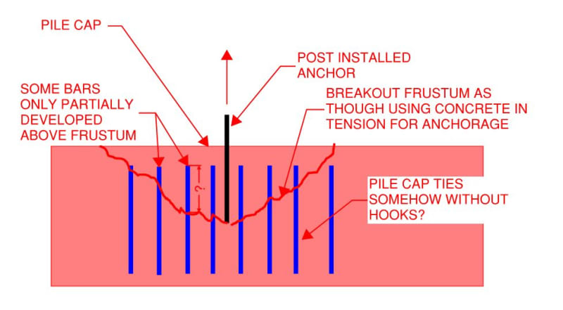
Is this what we're doing? If so, my thoughts would be as follows:

1) You can calculate capacity based on the concrete tensile/breakout capacity and, if your code allows it, take a bump for "supplementary reinforcement". Usually something minor to the tune of 15%. This is not really RC concrete design but, rather, "anchorage" in the modern concrete design sense.

2) Using strut and tie methodology, or a simplified version of it, you can use the vertical ties for your tension capacity and utilize partial bar development/anchorage where that is what you have available to you. This is really RC concrete design. You will be sacrificing some connection ductility with this route so be aware of that if ductility is important to your situation.

3) In my opinion, you cannot combine #1 & #2. Mobilizing the rebar per #2 requires already having developed the cracks that are implied by #1. So it's an "either or" case rather than a "both together" case.

c01_reaqvr.jpg
 
Thank you for the informative image KootK.

This is exactly the image I was going to attach. The one exception is the post-installed anchor's frustrum originates higher on the post-installed (black) anchor if one is back-calculating the Hilti HVU data. From this data, one could conceptualize the cone originating as high as 49% up the post-installed anchor. The grey lines in the attached (hi-jacked) image are relevant. I can agree with those who say this is counter intuitive, but the Hilti HVU capsule numbers back it up.

I tend to agree with all of your statements; especially #3. It should be one mechanism's job, and not both. Cracking would tend to mobilize the reinforcing steel tension resistance.

In the project I'm working on, the solution is based purely on #1 without considering supplementary reinforcement. Therefore, in-line with your #3 recommendation.

Thanks to all.

PC
 
 https://files.engineering.com/getfile.aspx?folder=11ad81a9-89f1-46d4-8a4c-a05661047019&file=Image.png
pbc825 said:
Thank you for the informative image KootK.

You're most welcome. I'm glad that I guessed close.

pbc825 said:
...hi-jacked...

Extra utility for my sketch... all the better.

pbc825 said:
I can agree with those who say this is counter intuitive...

I do find that conclusion intuitive actually. I've always wondered how one can guarantee that any number of the infinite numbers of [breakout frustum + bond failures] don't occur in these situations. In regular bar anchorage, I belive that it's customary to assume that you loose a little wedge of concrete where the bar first enters the concrete substrate. That strikes me as similar. I've reconciled myself to the notion that, in our sphere, test results often have to trump esoteric theoretical concerns in order to keep thing moving forward.

pbc825 said:
...but the Hilti HVU capsule numbers back it up.

If you return to this thread, and can spare the time, would you post a brief outline of how approached that reverse engineering exercise? It doesn't need to be numerical or anything. Conceptual only would suit me fine. I'm not challenging your method. Rather, I'd like to learn how to do it myself as it's something that I've been curious about and have never thought to approach in the manner that you have.


Thanks for the comments KootK.

Regarding your last comment, I have the following to report:

I've used an approach that I've adopted from the pullout resistance of a cast-in-place anchors with an embedded head. The failure cone (or frustrum) is characterized by a 45 degree cone originating at the embedded head. For calculating the factored resistance by this failure mode, one calculates the plan area of the cone base and multiplies the modulus of rupture (fr, effectively tensile strength of the concrete, CSA A23.3-04 clause 8.6.4 defines this as 0.6*lambda*sqrt(f'c),f'c and fr in MPa, and lambda is 1.00 for normal weight concrete) and partial material resistance factor (phi c = 0.65 in Canada). Tr = phi c*Acone*fr. For calibration to Hilti epoxy anchors numbers, I drop the partial material resistance factor.

In back-calculating the Hilti HVU numbers, I use the concrete strength properties noted by Hilti (4,000 psi, ~27.6MPa), and calculate the cone area that would equate ultimate Hilti tension resistance to the CSA ultimate numbers.

For example,
Ultimate Tension Hilti, 3/4"diameter fractional anchor embedded to 13.25" based on concrete failure = 61.23 kip (f'c = 4000 psi, fr = 457 psi)
Equivalent cone area = 61.23kip/457psi = 134 in2
Equivalent cone radius = (134in2/pi)^0.5 = 6.53 in
6.53 in/13.25 in = 49% (note, this is the lowest value returned for the table I was using)
We've therefore, conceptualized the post-installed epoxy anchor cone as originating 49% of the anchor bolt's nameplate embedment.

If failure planes overlap from multiple anchor bolts, I'll calculate group resistance based on the intersection of these cones rather than the ultra-conservative reduction numbers Hilti recommends using.

I hope that helps.

PC
 
I believe KootK's original diagram is fairly accurate, in that the potential failure cone begins where the resistance of the anchor begins. If the embedment is deep enough that the potential failure surface provides more capacity than the anchor itself, then the capacity is governed by the tension failure of the steel, but the size or depth of the potential failure cone in the concrete doesn't change; it just doesn't break out of the concrete.

Rod Smith, P.E., The artist formerly known as HotRod10
 
BridgeSmith, I won't argue that I have a perfect model. I'm not expecting it to be code-adopted any time soon. I've just found it useful. Could be a different angle, and bond strength is included in the Hilti results.

I will point out the Hilti data I'm referencing is strictly related to concrete or bond failure. There are separate tables for steel strength in the Hilti literature I referenced.

PC
 
BridgeSmith, KootK's sketch accurately depicts the breakout cone for a headed anchor, not for an epoxy anchor. A headed anchor develops its strength through bearing at the head and therefore that is the plane where breakout must start. However an epoxy anchor develops along its entire length, so predicting the breakout isn't as simple as it's breakout failure can also include a pullout or epoxy shear failure at its end.

pbc825, for what it's worth, that is the best model I have seen someone use to come up with the breakout cone for an epoxy anchor. I would be comfortable with that.
 
Status
Not open for further replies.

Part and Inventory Search

Sponsor