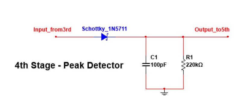
Hi, I am building a peak detector and voltage comparator for my returning signal of the ultrasonic transducer.
Below are the circuit diagram of peak detector and voltage comparator:


And below are the screenshot of oscilloscope after peak detector and voltage comparator:
[URL unfurl="true"]https://res.cloudinary.com/engineering-com/image/upload/v1487646346/tips/pic_62_2_ja67vl.bmp[/url]
[URL unfurl="true"]https://res.cloudinary.com/engineering-com/image/upload/v1487646378/tips/pic_62_1_qltlhp.bmp[/url]
As you can see, it kind of works, it detect the peak at the very beginning, however, what I am interested is the returning signal after the first pulse (the signal that appears in the middle of the screen), and my peak detector is not able to detect it.
Any idea about how to do it?
Thank you.
Below are the circuit diagram of peak detector and voltage comparator:


And below are the screenshot of oscilloscope after peak detector and voltage comparator:
[URL unfurl="true"]https://res.cloudinary.com/engineering-com/image/upload/v1487646346/tips/pic_62_2_ja67vl.bmp[/url]
[URL unfurl="true"]https://res.cloudinary.com/engineering-com/image/upload/v1487646378/tips/pic_62_1_qltlhp.bmp[/url]
As you can see, it kind of works, it detect the peak at the very beginning, however, what I am interested is the returning signal after the first pulse (the signal that appears in the middle of the screen), and my peak detector is not able to detect it.
Any idea about how to do it?
Thank you.
