Continue to Site

Eng-Tips is the largest engineering community on the Internet

Intelligent Work Forums for Engineering Professionals

  • Congratulations KootK on being selected by the Eng-Tips community for having the most helpful posts in the forums last week. Way to Go!

Peeling Force Calculation

Status
Not open for further replies.

SSergey

Mechanical
Feb 8, 2021
12
Hi There,

I need some guidance/help with weld calculation.
Imagine that you have a C-channel converted to a rectangular tube by welding additional flat plate to it, "CI", with fillet weld. Internal dimensions of a channel are 2"by 3". Now we fixed one end of this welded rectangular tube (c-channel + flat plate) and insert a smaller rectangular member (1.9"X2.9") inside of it (so, we have a cantilever telescopic boom). We apply some force at the tip of a small rectangular tube. Due to some dimensional clearances, small rectangular tube slightly pivots around the edge of the welded rectangular tube until the top edge (from the inserted side) of a smaller tube touches the top internal surface of welded rectangular tube.
Question: how can we estimate the peeling force acting on the fillet weld? C channel is on top of the flat piece.


Thank you,
Sergey
 
Replies continue below

Recommended for you

FEA will be your best bet.
You have a moment, that will be divided in two point loads (fulcrum point and top edge of smaller bar) and the distance between both.
The fulcrum point will be critical, as the other point will be reacted by a weld that goes in two directions away from the point of contact. Fulcrum point only has a weld on one side of the contact point.
Depending on the magnitude of the forces, I'd say few mm will react the point load at the fulcrum, before plastic redistribution will take over.
Manually, I'd check against the rigidity of the C-channel + plate, and make sure the weld is as strong as the plate.
 
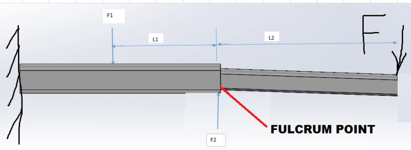
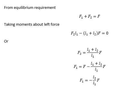
Solution from statics is given below:
image_h4pkcj.png


image_poe7od.png

The l1 value will depend on the clearance between members which can be calculated from geometry. It can be seen that peeling force F2 can be very high if l1 is small.

Engineers, think what we have done to the environment !
 
Hi SSergey ,

You have some alternatives depending on the sensitivity of calculation you want,

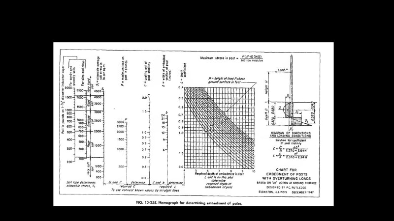
1- Assume the connection is pocket type connection used for precast column foundations. In this case, assuming the stress distribution will be linear,the moment arm between the resultant resisting forces will be around 0.6 L1 and the max . moment for the smaller size beam will not be at fulcrum point but will be somewhere at L2+ 0.15 L1. You will somehow similar approach for embedment of lighting poles etc...

2- You may assume L1 portion beams on elastic foundation...You may look some handbooks. One of the reference books :
Beams on Elastic Foundation_ Theory with Applications in the Fields of Civil and Mechanical Engineering (Miklos Hetenyi)

3- You may develop FEM ..

You may look to Design moment of an embedded steel post
thread256-478012

embedment_of_poles_n0eewx.jpg
 
Thank you so much to everybody for the response. I forgot to address important question.
How can we calculate the strength/maximum stress of the weld once we know the peeling force?
 
Depending on the code you work with.
I'd say, formula 4.1 from EN 1993-1-8
 
Somehow I got stuck. My small rectangular tube acts as a pry bar. I made an assumption and considered this case as a weld joint loaded in torsion with the length of the "resisting" weld bead equal to its throat size. Am I right with this assumption?
 
Draw a cross section of the larger tube, and see how the smaller bar acts on the larger tube. I don't see any torsion.
 
Please, see these images.


I ran FEA with nonlinear contact. Clearly it says about local plastic deformations and high stresses in the vicinity of the contact. Peeling might be initiated and the weld will not support my load. Yes, the problem is getting complicated if I need to consider the plate bending as well. It might put me on the conservative side.
Need to know the manual way (approximately) of checking the FEA results.
 
"@kingnero (Mechanical)8 Feb 21 17:23
Draw a cross section of the larger tube, and see how the smaller bar acts on the larger tube. I don't see any torsion."

I "virtually" bonded the small rectangular tube to the large one at the point of contact (fulcrum point) and noticed my fillet weld being in torsion. The length of this bond is very small (equal to the length of the hertz contact). However, I assume that the weld length resisting to this torsion is equal to its throat size (roughly). It can be longer than that but also can be even smaller.
 
Tmoose (Mechanical)8 Feb 21 17:34
I think you need a detail like this -

Did you attach anything? It tells me "illegal character"
 
To remove a lot of uncertainty I suggest to weld a rectangular reinforcing ring where F2 is applied and assume that whole F2 load is taken up by this ring.Assuming that the whole beam length is designed adequately for bending loads.

Engineers, think what we have done to the environment !
 
"goutam_freelance (Mechanical)8 Feb 21 19:21
To remove a lot of uncertainty I suggest to weld a rectangular reinforcing ring where F2 is applied and assume that whole F2 load is taken up by this ring.Assuming that the whole beam length is designed adequately for bending loads."

Thank you for proposed solution.
Let's assume for now that we need to calculate the current state (weld ring is not present, only friction and wedging effect).
 
Below is a better link to the image from my 8 Feb 21 17:34 post.
It is Standard practice on trailer hitch receivers with more homogenous material but possibly more severe and cyclic loading.


Some would say FEA and welds are mutually exclusive. The actual geometry is pretty far from what is, or perhaps even can be modeled.
 
@ Tmoose, neither link works for me...

Attached a drawing of how I imagine the situation. I altered the shape of the forces after I initially drew them, hence the weird shape. It is the final (parabole) diagram that counts.

I'd assume distribution of half the force towards the back of the C channel (left side of the drawing), and half towards the plate (right side) through the weld (in red).
I'd not be concerned with the rotation of the weld, because the bottom part of the C-channel will (simplified) "see" two point loads, not a uniform distributed loading. This will help in order to minimise bending. It's essentialy vertical shear through the weld.
Question remains, what is the length of the weld that you need to take into account to react this force.
 
 https://files.engineering.com/getfile.aspx?folder=662565f0-31f9-439c-ad11-8e852ddd77ad&file=20210210171900_001.pdf
Does your channel really have sharp corners where the web meets the flanges?
Are the relative thicknesses as shown in the Feb 10 image? Your original post suggested .05" thick walls I think.
The actual loading would be useful to now.

What is at risk if the outer "tube" peels open, or the inner tube buckles or kinks?

Could you buy 2 channels with shorter flanges ? []

Attached is a picture of the outer tube detail I think you need.
It is Standard practice on trailer hitch receivers made with more homogenous material but possibly more severe and cyclic loading.

Some would say FEA and weld analysis are mutually exclusive. The actual weld geometry will be pretty far from what is, or perhaps even can be modeled.
 
 https://files.engineering.com/getfile.aspx?folder=bb8262e8-dfcd-4972-b6de-3d359cdc30fe&file=20PM68_AS01.jpg
I apologize for my message delay.
Thank you everybody for sharing your ideas!

@ Kingnero
Your diagram should be rotated by 90 degrees clockwise. Flat plate is horizontal, and takes the compression load from the inserted member.

@ Tmoose

"Does your channel really have sharp corners where the web meets the flanges?" Would you mind clarifying the question, please?
"Are the relative thicknesses as shown in the Feb 10 image? Your original post suggested .05" thick walls I think.
The actual loading would be useful to now" I have never mentioned any thickness in my messages. My first message tells that clearance does exist between two members, and it leads to "some play between the members" which leads to a line contact. I hope this clear.

I failed to title my thread properly. It should have been titled "how to estimate a weld strength under the effect of a peeling force"

Not really trying to find solution (or "way around") to this case. I need to run theoretical calculations and prove whether this system would fail or FOS is above a reasonable doubt. :)

Once again, Thank you everybody!


SSergey said:
@ Kingnero
Your diagram should be rotated by 90 degrees clockwise. Flat plate is horizontal, and takes the compression load from the inserted member.
Should have posted such a diagram yourself, and don't have us guessing.

And I'd call it shear, but it's indeed a combined load within the weld.
 
Typical rolled channel has radiused inside corners and the flanges are tapered on the "inside" faces.


Channel "cold formed" from sheet or plate will usually have inside and outside corners radiused.
 
Status
Not open for further replies.

Part and Inventory Search

Sponsor