Eng-Tips is the largest engineering community on the Internet

Intelligent Work Forums for Engineering Professionals

  • Congratulations waross on being selected by the Tek-Tips community for having the most helpful posts in the forums last week. Way to Go!

PEMB Hairpins for Side Shear Breakout

Status
Not open for further replies.

Buleeek

Structural
Sep 5, 2017
98
0
0
PL
Hello,

I am designing a PEMB foundation. The base plate will sit on a pier (42"x42"x24"deep) which will rest on the actual footing (8'x8'). I am having a difficult time with the side shear breakout in the pier. For the front shear breakout I will provide hairpins wrapped around anchor bolts, but what would one recommend for the side shear breakout ? As I mentioned it is on a pedestal, so there is no possibility of installing hairpins in the other direction. Can the "regular" hairpins help with side shear breakout?

Thanks in advance.
 
Replies continue below

Recommended for you

Per ACI 318-14, Section 17.5.2.9 (p. 255), can you rely on reinforcement developed beyond the breakout surface? I suppose you're saying no. What if you provide ties around the anchors?

For maybe a better answer:
Can you provide a quick sketch including anchor bolt locations? Does the pedestal extend up 24" beyond top of slab? What is the shear force you need to resist?
 
Buleek said:
Can the "regular" hairpins help with side shear breakout?

The anchor reinforcement needs to transfer tension and is most efficient at this along its long axis.

You want to orient the axis of the anchor reinforcement with the direction of concern. Maybe more hairpins oriented perpendicular to the ones you already have? Like Eng says a sketch would be helpful.
 
Unless you have monster shear forces you should be able to use the ties to resist your force. Check out "Design of Anchor Reinforcing in Concrete Pedestals" by Widianto, Patel, and Owen. There is an example of how to design shear anchor reinforcing.
 
One thing I'd like to mention about using hairpins to resist these forces is that the hairpins themselves only transfer the load into the slab. The slab must also resist the load.

If your hairpin resist 25 kips, I calculate what width of slab would be needed to resist that force by friction, then I make the hairpin long enough, and with a sufficiently wide angle so that it spreads over that width of slab which is needed to resist the force.

Please for the love of god do not simply select a hairpin based of As*Fy then just develop into the slab without thinking about where that load goes.

Seen it a few times in the past few years where engineers did exactly this, they had the correct hairpin bar diameter, but only went Ld into the slab. What do you know the slab cracked and essentially lost its ability to transfer seismic shear from the anchor.

 
Thanks for the responses. See attached the sketch you have asked for. Basically, to resist the bracing reaction I only have the pier, since hairpins will not fit. Or maybe they somehow will ? Let's assume there is a 4-6" concrete slab with edge on the perimeter of the building (top of slab = top of pier).
 
 https://files.engineering.com/getfile.aspx?folder=52433741-4612-4df0-bad1-bc3816a94d79&file=SIDE_SHEAR_BREAKOUT_ISSUE.pdf
Seems like if your hairpins restrain the back side of the anchors you can't get sideface blowout. But you might also consider looking at the ties and doing a little strut and tie on your pier to resolve the shear in that direction.

Link
 
driftLimiter said:
Seems like if your hairpins restrain the back side of the anchors you can't get sideface blowout.

I think that Buleeek is concerned with a shear failure. Side face blowout is a tension failure mode.
 
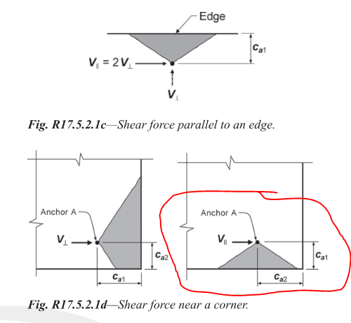
Yes you're correct my bad for poor terminology. This is the breakout I thought we were talking about:
side_blowout._ob4yqz.png
 
driftLimiter, Yup, that's my understanding as well in terms of the failure mode. I think it's referred to as "concrete breakout strength in shear." The terminology definitely gets confusing and Chapter 17 overall is not easy to follow. I'm currently going mildly insane trying to develop some in-house software for this analysis.
 
Yea it doesn't get a special name but this figure shows how to evaluate the loading of it. Have fun with making a software for anchorage calcs, it's enough to drive anyone mad. Throw in post installed anchors and you will go completely bonkers.

Anyway to the OP, the hairpins you already have can help resist this load and from the ACI figure above you can determine the loading needed to proportion the hairpins. But Like I mentioned early I would wrap the outside of the anchors.
 
For that layout, I would put some upturned u-bars between the anchors. You should have lots of space there to develop #4 hooks on both sides of the breakout cone.
 
Just for "fun", I ran an analysis of this layout in a tool I created for anchorage design. Assuming 3,000 psi, cracked concrete, 3/4" diameter F1554, Gr 36 ABs spaced on a 9"x9" grid, no supplemental reinforcement, and some other conservative assumptions, for your "Bracing Reaction" load acting in the positive x direction (to the right), I get an available concrete breakout strength in shear of about 14 kips.

The controlling case for breakout is actually the perpendicular (right side) of the pier failing. The breakout capacity of the parallel side (top side per plan view) is roughly double that. The capacity calculated in this software is based on the assumption that only the upper right AB is resisting the entire shear force, which may be quite conservative (although I have my reasons). If the anchor bolts are fully connected to the base plate (or if this happened to be an embedded plate with shear studs instead), then it would be more reasonable to use the row of ABs located farthest from the breakout surface to calculate the capacity.

In case you were hoping to use reinforcement to resist the breakout failure but aren't able to fully develop the rebar as required by ACI 318-14, Section 17.5.2.9, it's still possible to get some additional benefit of reinforcement. The psi_c_V factor (see Section 17.5.2.7) used in the breakout capacity calculation can provide an increase of up to 40 percent versus cracked concrete with no reinforcement. This 40 percent increase would be realized if there is reinforcement of a #4 bar or greater between the anchor and the edge and the reinforcement is enclosed within stirrups at 4" o.c. max. In addition, a greater phi factor (Section 17.3.3) is also allowed where supplementary reinforcement is provided.

This doesn't address your original question, but in case it's of value, based on the analysis that I ran, the controlling strength is actually limited by the steel strength of the AB and not on a shear breakout failure. Again, this is based on the assumption that a single AB is resisting the full shear force, which might not be a reasonable assumption in your case. As noted, the calculation is also based on a 3/4" diameter, grade 36 AB which might not be the case for you.
 
To add to driftLimiter's response,
If you're using these hairpins to distribute load into the slab, make sure you've considered the spacing of your slab control joints. Depending on your slab design, you may require control joints at maximum intervals. If you're using a section of slab to resist load, you don't want a joint running through this width of slab. For situations like this, it's helpful to illustrate the location of these joints on plan.
 
I thought the original question was relating to local breakout capacity of the anchors within the pier. I think this is getting conflated with questions of global stability and global load path.
 
driftLimiter said:
One thing I'd like to mention about using hairpins to resist these forces is that the hairpins themselves only transfer the load into the slab. The slab must also resist the load.

Also need to check the elongation of the slab rebar.
 
Status
Not open for further replies.
Back
Top