Continue to Site

Eng-Tips is the largest engineering community on the Internet

Intelligent Work Forums for Engineering Professionals

  • Congratulations cowski on being selected by the Eng-Tips community for having the most helpful posts in the forums last week. Way to Go!

PEMB - How to Control Displacement 3

Status
Not open for further replies.

TAK19

Civil/Environmental
Nov 1, 2021
7
Good Morning,

I am designing the Pre Engineered Metal Building. I am using a Etabs 2016 to perform the design.
I have noticed that the displacements value I am getting are too high with respect to L/360,L/400 requirements.(Owner require the exterior walls to have deflection limits of L/360) I need help in controlling this high displacements of the joints.
I know the common methods used in the industry to control the lateral movement but my problem with them are as follow:
1. Cable or Rod Bracings - Cant use as I have lots of windows in most of the walls
2. Portal Frame - When I added a portal frame to the rigid frame the software gives me warning that the columns are overlapping and also its not reducing the displacement noticibly.
3. Wind Column - Don't know how to add them in Etabs.

Questions :
1. How can I fixed the problem in item number 2
2. I have tried all known methods to make the rod bracings tension only but I am unable to.(in Etabs)
3. The largest displacement value I am getting from the software is 7 inches .I am sure I am missing something important because this building is only 4000 sqft with mono slope roof eave ht of 18 ft.

I would Highly appreciate if you all experts can guide me on this.
 
Replies continue below

Recommended for you

Dold : The software joint displacement value exceeds the limits of H/400 but the are within the 0.02H limit. Also please confirm my understanding that the etab software will not going to have any limits for lateral deflection/displacement?

The thing is that software does shows utility ratios well below 0.9 for all the members.

Yes the same load combinations I used to check the frames and some of those combinations values exceed the criteria of H/400.

Also there is not much commentary about the stucco attached directly on the metal wall panel. I am unable to find any guidance for this kind of methodology.
 
I'm not sure exactly what information you're lacking from the software. It doesnt matter if its ETABS or any other software. A joint displacement is a joint displacement...? It sounds like you know that you are exceeding H/400 for your serviceability wind load cases, so, you need a stiffer building unless your client agrees to a less stringent criteria. Are you sure that you have chosen a suitable windspeed (10 year, 50 year, 100 year....etc) that you are checking your drift against? 7 inches is a lot for 18ft tall building.

To be sure: What windspeed are you using to calculate your wind pressure for serviceability (drifts) and what windspeed are you using for strength level wind pressures?

Compare wind displacements to H/400. Compare seismic (amplified) displacements to 0.02Hx.

Is there someone in your office who has done this before? Or used ETABS? Unless I'm missing something, this seems like something that a PE should be able to sort out in a few minutes...?
 
Fix base the columns and heavy-up the bottom of the columns. PEMBs traditionally have pin-bases, but they can be fixed just like any other columns. Fixing them takes costs out of the PEMB and puts it into the foundations. How wide is the frame and ho many interior columns are there?
 
I'm a longtime PEMB engineer and basically what you're trying to do is impossible.

Other posters are correct that PEMB companies use sophisticated software specifically designed for PEMB systems that take into account millions of industry standards, tips, tricks, etc. PEMB design software optimizes rigid frames and light gauge secondary systems and can be configured for the exact specifications of that PEMB company's factory so that it only designs things that they are set up to produce. It also designs every single weld, connection plate, bolt, etc. at the same time.

There are literally tens of thousands of things you'd need to have an understanding of to reinvent this wheel. Like RISA or any other engineering design software, these have been evolving for years and continue to evolve to take meet code requirements and update functionality. Even if you were the smartest, most experienced person in the world, you don't have the time.

Also, questions like the main one you're asking about deflection are trade secrets. The PEMB industry operates differently from consulting. In consulting, you're firm is selected before the total weight of the building (steel budget) is known. You may be asked to value engineer a structure to reduce cost but you're not competing against a different consulting engineer to see who has the least expensive system.

PEMB companies join a job after much of the work of the architect and engineer is complete. We submit bids to furnish and erect the PEMB portion of a project so we are heavily incentivized to find the lightest (least expensive) way to engineer a solution. All this is done by an engineering estimation team to produce a bid. For the jobs we win, it actually gets designed by engineers. So if I were to stumble on a new approach that would allow us to furnish a lighter building that still meets the drift requirements, for example, I'm keeping that information only for my company. It gives us a business advantage.

Something else I'll point out are some of the reasons it's difficult to reproduce PEMB results in traditional software. Many programs, like RISA, allow you to use tapered members but automatically assign a Cb factor of 1.0. That will make any PEMB structure you try to duplicate appear to be failing. Another is that those programs aren't designed to use different unbraced lengths for the top and bottom flanges. PEMB software braces an outside flange anywhere there is a purlin or girt but only braces the inside flange where a flange brace exists.

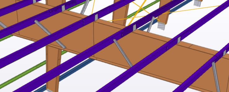
PEMB_Rigid_Frame_Rafer_e6zkek.jpg


I could go on and on but I hope I've given you enough information to allow you to get away from your impossible task and design something that's actually feasible and that you're comfortable with.
 
Ron:

I had tried to do change the support from the pinned to fix but no significant success. I was able to meet the Owners requirements by adding C-Channel bracings in few walls .The frame is 80' wide and 3 spans only.

SnadwichEngineer :

I highly appreciate your detail message .I wanted to see if there is anyway we could talk on phone or by email to discuss this further.

 
Status
Not open for further replies.

Part and Inventory Search

Sponsor