Continue to Site

Eng-Tips is the largest engineering community on the Internet

Intelligent Work Forums for Engineering Professionals

  • Congratulations KootK on being selected by the Eng-Tips community for having the most helpful posts in the forums last week. Way to Go!

Per Unit Impedance 3 Winding Transformer for simple fault current calculation

Wfg42438

Electrical
Apr 10, 2017
70
Hello,

I wanted to see if anyone has a good reference of how to determine the per unit impedance of 3 Winding XMFRs ?

I have a very basic fictious system shown below and I'm trying to determine how to by hand calculate the LG and 3 Ph fault currents at Bus 23, 26, and Bus27 but I'm not clear on how to represent the 3 winding XFMR.
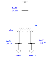
1734308041748.png

In the software package whats entered is :
MVA per winding
Zps, Zpt and Zst plus the X/R ratios.

Lets assume each lump load represents a 100% motor load

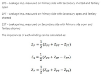
I found the following equations but cant seem to match the software's result which tells me im making a mistake when finding the three impedances they propose as :

1734308188771.png

Where im stuck is how to determine which of the three equations above to use to determine the equivalent impedances for the positive and negative sequence networks.

Something tells me that depending on the fault location some combination of these impedances applies.


Any guidance on this would be much appreciated.
 
Replies continue below

Recommended for you

Something to be aware of;
The delta will transfer power from the healthy phases to the shorted phase.
The current of this transferred power will be limited by the impedance of the primary to the delta and by the impedance of the delta to the secondary.
In the example, the total fault current is limited by the grounding resistor.
This is only important to show you that you are showing a three winding wye transformer and trying to use a formula for a wye/delta/wye transformer.

In your example, without motor loads, bus 26 and bus 27 could be treated independently and the third winding ignored.
The contribution of the motor loads complicates things.
With a single line to ground fault, the motors will continue to be powered by the two healthy phases.
The rotor will be developing equal back EMF on each phase.
This will back feed into the fault.
Additionally, the motors on the unfaulted bus will backfeed through the transformer to a fault on the other 13.8 kV bus.
Your challenge is to find the correct formula to determine the impedance between the 13.8 kV windings, and to determine the motor contributions.
How many times have we heard;
"Motor contribution to a fault will last for several cycles."
That is for a three phase short where the motor losses power and de-cellerates.
For a line to ground fault, the motor contribution may persist until the motor circuits are cleared.
And.- The motor contribution will be supported by the healthy phases.
Thank you for the insight is there any way you can point me to a good source to obtain the relevant impedance values for my particular case?
 
The positive and negative sequence impedances in a transformer should be equal. What is on the nameplate and/or test report?
 

Part and Inventory Search

Sponsor