Continue to Site

Eng-Tips is the largest engineering community on the Internet

Intelligent Work Forums for Engineering Professionals

  • Congratulations SSS148 on being selected by the Eng-Tips community for having the most helpful posts in the forums last week. Way to Go!

Perfect Form Not Required on Flatness with Parallelism 3

Status
Not open for further replies.

jrhodges

Aerospace
Sep 2, 2015
4
I am looking for some help with the following situation (see image). I've been looking through ASME Y14.5-2009 and other guides and can't find precisely what I'm looking for.

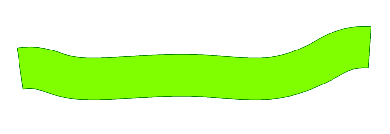
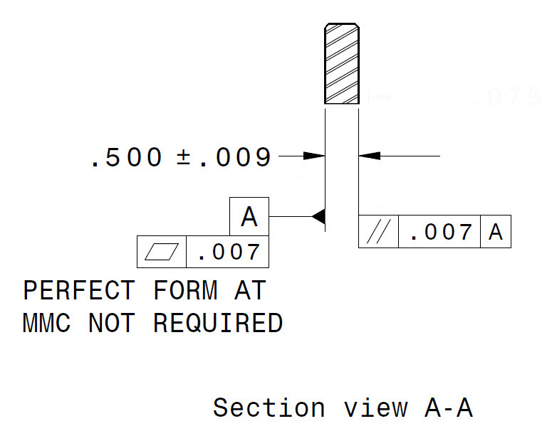
I'm trying to determine how the note, "Perfect form not required at MMC" effects this tolerance scheme. I'm primarily concerned with how this affects envelope and if this may have an effect on the thickness variation within the part itself. Ultimately I'm trying to see what could this part actually look like?

Thanks for your help!

PF_not_req_-_flat_para_fmkqqo.jpg
 
Replies continue below

Recommended for you

I guess the part can be a banana shape with all local sizes being between .491 and .509.
From the datum A (created from the highest points of the datum feature A) you are going to have two perfect parallel planes .007 apart tolerance zone and all the points of the opposite surface should fit in this tolerance zone .007.

Flatness and parallelism of the faces with each other will not be restricted to .018.


I do have a question for you: how did to manage to attach a picture and not using the attachment? I am trying to do the same. Please can you share your secret. Again, having the picture but not as an attachment. How would you do that? What picture format is needed to be able to use it as yours and be visible on the screen without being attached?


greenimi,

To post the image, click the Upload Image icon (it is two to the left of the smiley face icon).

 
Thank you CoryPad. I learn something new today.
 
Rule number one would require perfect form at MMC (.509), i.e. zero flatness and parallelism. This call out requires .007 flatness and .007 parallelism for any thickness between .491 and .509. This is exactly how the part would be specified under ISO without the envelope rule.

----------------------------------------

The Help for this program was created in Windows Help format, which depends on a feature that isn't included in this version of Windows.
 
jrhodges,

Good question. I believe that the feature could have an envelope of 0.516 and still satisfy the tolerances. It could have a local thickness of 0.509 everywhere, and be bent by 0.007.

Evan Janeshewski

Axymetrix Quality Engineering Inc.
 
Thanks for all of the replies, this is really helpful. So, as far as I can understand, all of these scenarios are possible given this method:
flat_par_II_ms2rkd.jpg

Is this assessment correct?
 
Why the two .007 tolerance zones are parallel with each other? Do they have to be?
 
Sorry, "A)" and "B)" this way is actually more accurate, since datum A will be determined by the surfaces high points:
Yes, the tolerance zones are necessarily parallel. Flatness is determined by the peak to peak (surface high point to surface low point) variation in the surface, those high points then define datum A (as if the plate were resting on a surface table) and finally the parallelism tolerance zone is defined as two planes parallel to Datum A separated by the specified tolerance, which the part surface must fall into.

flat_par_II_sobby2.jpg
 
jrhodges said:
[Yes, the tolerance zones are necessarily parallel.]

I am a little bit confused. I don’t disagree with any of the statements above, but I do not know why the two .007 tolerance zones have to be parallel with each other to get a conforming part?

Please correct me if I am wrong.

Flatness tolerance zone can be moved, translated, rotated in any way until you get all points of the surface to be in it. If you can do that the flatness requirement is meet.
Parallelism tolerance zone has to stay perfectly parallel with datum A (datum driven from the datum feature A by contacting its highest points) and you can move the tolerance zone up and down or left and right until you get all the points of the surface you are checking the parallelism of to be into the tolerance zone.

Now, if a part meet flatness and also meet parallelism requirements, BUT the two tolerance zones are not parallel with each other, will you consider the part non-conforming? That was my main question.

Remember, the flatness tolerance zone can float (no datum restriction from flatness) and also parallelism tolerance zone can float (considering the orientation cannot locate and also about the candidate datum set, if the datum feature A is a rocker). Am I right?

Again, I am asking. Please be gentle. If I am wrong won’t be the first time (happened before even in this thread, that’s way I have deleted by post after I saw Evan’s post regarding the .516 size dimension).
 
greenimi,

You're right - the two zones don't have to be parallel to each other. I suspect that the as-produced examples jrhodges came up with just happened to come out that way. But we can dream up examples in which the fitted Flatness zone for datum feature A is not parallel to the high-point datum plane. Here's a possibility:

FlatnessParallelism1_pkqsue.png


Let's say that both sides of this part are flat within 0.007. I think that it could either pass or fail the Parallelism tolerance of 0.007, depending on which side is chosen as datum feature A. This starts to get into the rabbit hole that GD&T becomes.

Evan Janeshewski

Axymetrix Quality Engineering Inc.
 
jrhodges

Your image for example "A" is the only one that could result with the note:
"PERFECT FORM AT MMC NOT REQUIRED"
or
In ASME Y14.5 2009 the "Independent" symbol (an encircled "I") would be next to the size tolerance

Perfect form at MMC does NOT include perfect orientation.

ASME Y14.5 2009 para 6.2
....An orientation tolerance does not
control the location of features....

Features of size can not exceed size limits (high or low limit)


Orientation control tolerances fall within the size limits

It appears to me that:
Example B(s) exceed size limits. Out of spec.
Example C(s) are withine size limits. Within spec. MMC note has no effect.

 
You are correct, I misspoke, the zones themselves don't need to be exactly parallel.
 
Dear All,

I have only one simple question. What would happen if no specific requirement is indicated in the drawing for datum A? In other words keeping the parallelism while removing flatness 0.007?
How the guy who may check the part in production can locate datum A considering ISO standard?
It is possible to use functional gauge considering ISO to check the part?

Many thank in advance.

Filippo


filippoGDeT,

You sit the part with datum[ ]A on your reference flat. You run a dial indicator on the opposite face. The dial moves by no more than .007".

Datum[ ]A is not the whole face. It is whichever three points extend down to contact the reference surface. In theory, datum[ ]A could be extremely not-flat. I am not sure what happens if datum[ ]A is concave.

--
JHG
 
Let’s assume for a moment the part is “banana shape”. Concave/convex surfaces.

Which surface is datum feature A? What would you do?

Candidate datum set versus highest points?

Is “A” the convex surface? Or it is the concave surface? Or could be both?
 
Status
Not open for further replies.

Part and Inventory Search

Sponsor