Continue to Site

Eng-Tips is the largest engineering community on the Internet

Intelligent Work Forums for Engineering Professionals

  • Congratulations IDS on being selected by the Eng-Tips community for having the most helpful posts in the forums last week. Way to Go!

Permanent magnet generator question

Status
Not open for further replies.

Teppo

Electrical
Jun 6, 2019
7
Hi all,

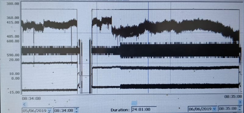
Something weird is happening to this generator. It is driven by VFD that is connected via DC-bus to a another inverter that supplies the power to grid. At some point Voltage and current supplied to grid starts to oscillate. Does anyone have a idea what could be causing this behavior? See attached picture.

Trends from top to bottom:

Generator voltage AC
Grid voltage AC
Grid converter DC
Grid current
Grid power (Kw)
 
 https://files.engineering.com/getfile.aspx?folder=30950868-8188-469f-afab-3346630fbb08&file=trends.jpg
Replies continue below

Recommended for you

Inlined for everyone here:

trends-1_usacjb.jpg


Keith Cress
kcress -
 
Hi Teppo, welcome to Eng-Tips.

I'm a bit confused because I've never heard of a GENERATOR being driven by a VFD. VFDs usually drive motors.

Is the VFD actually driving a motor that is then turning a generator?

Keith Cress
kcress -
 
Hi,

No, generator is started as motor and then "switched" to generator by applying external moment to rotor. It's high a speed machine and the the generator nominal is frequency about 1700Hz, so for obvious reasons it cannot be driven without VFD.
 
Hi Teppo,
1. could you give more informations about lines of the graphs?
2. Normally when lot of signal is missing some protection system is activated and the control change in "safety protection" mode. in this case before and after problem you have no particular change and this give me indications that problems is in the measurements chain only
3.Could you paste indications about connections

Regards
 
Hi,

1. Not much, i'm not currently at site myself. The drops at about 1/3 from left on the graphs are normal shutdown procedure. the problem starts at about center of the trends. Time interval of trends is 24h. Data is read via bus to the control system and i really don't know is it manipulated/filtered etc. or how it is calculated by VFD.

Trends from top to bottom:

Generator voltage AC
Grid voltage AC
Grid converter DC
Grid current
Grid power (Kw)(- means to the grid)

2. yes it might be problem only in the measurement chain.

3. Sorry i don't understand the question.
 
What is your prime mover?

Bill
--------------------
"Why not the best?"
Jimmy Carter
 
It looks as if your generator voltage is a straight clean line.
The grid voltage is all over the place.
That is a lot of grid upset to be caused by a tiny 15 kW generator.
How about the whole picture?
What is driving the generator?
What type of loads are on the grid?
From the little information given we can only give WAGs. (Wild ASSumptive Guesses)

Bill
--------------------
"Why not the best?"
Jimmy Carter
 
Hi,

i don't have much more to work with.

Generator is connected straight to a substation (20kV >400V). I guess substation is about 1000kVA or more. I don't know what kinds of other loads are connected to same substation, but mostly motors i think. It's industrial site so there should be compensation batteries for reactive power.
The problem seems to start at random intervals and doesn't stop before restart.
 
There is a sharp step down, then back up which occurs about 1/3 of the distance along the time axis.
Does that have a known cause (in which case please tell us what's going on there), or is it part of the unknown behavior you are trying to explain?

=====================================
(2B)+(2B)' ?
 
Teppo (OP) said:
The drops at about 1/3 from left on the graphs are normal shutdown procedure. the problem starts at about center of the trends.
Teppo, you list five parameters but i can't identify 5 traces on your attachment.
Your output may be causing an interaction with an On-Load-Tap-Changer.


Bill
--------------------
"Why not the best?"
Jimmy Carter
 
Hi,

First trace is very easy to miss, because it is so linear, but it's there. As Waross pointed out the drop at 1/3 from the left is normal.
 
Hi,

Here On-Line-Tap-Changers are installed at 110 kv grid, however it can still be the cause of the voltage drop. Grid is something like this 400kv > 220kv > 110kv > 20kv > 400V.
 
I read the trend as about 14 kW output. Is this correct?
Is the substation owned by the utility or by the client?
What powers the generator?

Bill
--------------------
"Why not the best?"
Jimmy Carter
 
Hi,

I guess substation is owned by the client. 14kw is correct. Prime mover is a gas turbine powered by biogas.
 
First I would as soon as possible check the tap changer. It may be fine, but if it is switching between tap positions so rapidly as to cause those traces, it may not last long.
I suggest to first rue out the tap changer as the source of the problem and then move on to other possible causes.
Is it possible to get a trend of the grid voltage when the generator is NOT online?

Bill
--------------------
"Why not the best?"
Jimmy Carter
 
electricpete said:
There is a sharp step down, then back up which occurs about 1/3 of the distance along the time axis.
Does that have a known cause (in which case please tell us what's going on there), or is it part of the unknown behavior you are trying to explain?
Would you mind answering my question please? Thanks.

=====================================
(2B)+(2B)' ?
 
Pete:
WARoss said:
Quote (Teppo (OP))
The drops at about 1/3 from left on the graphs are normal shutdown procedure. the problem starts at about center of the trends.

Bill
--------------------
"Why not the best?"
Jimmy Carter
 
Status
Not open for further replies.

Part and Inventory Search

Sponsor