Continue to Site

Eng-Tips is the largest engineering community on the Internet

Intelligent Work Forums for Engineering Professionals

  • Congratulations KootK on being selected by the Eng-Tips community for having the most helpful posts in the forums last week. Way to Go!

Permanent Magnet Synchronous Generator (PSMG) - Searching for references and standards

Coco_HueHueHue

Electrical
Apr 8, 2018
48
Hello,

Currently working on a project where we integrate a Permanent Magnet Synchronous Generator (PSMG) into a Distributed Generation plant. I did that in the past for Asynchronous Generator and Synchronous Generator (field excitable), but never for PSMG. The unit is only 333kW. The general installation is a small hydro distributed generation plant.

Can anybody here help me find applicable standards or have a good book reference for that kind of equipment?
All I find is for large hydro unit or wind turbine or car industry. I couldn't find anything for small hydro units of this type.

Searching for information on:
- Functional description (how to drive the voltage output since there is no field excitation and how to put them online and manage their speed - I expect like a DSVC and a governor)
- Recommended Protection and Controls.

Thank you for any help anyone can give me on this.
Best regards,

Coco
 
Replies continue below

Recommended for you

You may have misunderstood the term Permanent Magnet Generator.
Before the advent of PMGs diesel generators supplied power to the Automatic Voltage Regulator from the main generator output.
Some AVRs had sense terminals to sample the output voltage and power terminals where power was supplied to the AVR from the generator output, either directly or by a small transformer.
Some AVRs combined sense and power into one pair of terminals.
This scheme was prone to voltage collapse where a fault or extreme overload would draw the output voltage down and as a result the AVR would not have enough voltage supplied to bring the output voltage back up.
The permanent magnet generator is a small generator that is typically mounted on the generator shaft, outboard of the back end bearing of the generator.
The job of the PMG is to supply power to the AVR.
The last few that I worked on generated about 220 Volts, three phase and were paired with an AVR that expected a 220 Volt, three phase, power supply.
PMG equipped sets avoid voltage collapse and tolerate block loading better than self excited machines.
When ordering a 333 kW generator a PMG may be standard equipment or it may be an extra cost option.
In the event of failure of a PMG or of a PMG AVR, a machine may, in some cases, be operated temporarily with a self excited AVR until spares arrive.
When using a self excited AVR on a system designed for a PMG, fault protection may be compromised and voltage dips due to block loading may be greater.
By the way, did you mean 333 KVA? Generator capacity is limited by KVA, not kW.
kW is a description of the prime mover's minimum capability.
If you need 333 kW, the generator nameplate will probably show:
416 KVA, 0.8 PF.
A 333 KVA machine will supply 333 kW only to a load of unity power factor.
A 333 kW load at unity PF is extremely rare in the real world.
I did that in the past for Asynchronous Generator and Synchronous Generator (field excitable), but never for PSMG
Did you use a CT supplied circuit to provide excitation boost to avoid voltage collapse?
This is not needed with a PMG and PMG AVR.
Your lineup will be:
Speed controlled by a governor that is controlling the prime mover.
Voltage control by set point on the AVR.
Load control by a 5% droop setting on the governor.
PF control by voltage adjustment.
PMG equipped generator and PMG ready AVR.
In a distributed generation scheme, you may generate 333 kW with a 333 KVA rated generator by running at unity power factor.
However you must consult your tariffs to see if running at unity PF will be acceptable.
Some tariffs will specify some amount of KVARs be supplied.
Your no-load, off-line from the grid, speed/frequency will be controlled by the governor.
Your on-line speed/frequency will be controlled by the grid.
Your loading will be controlled by the governor. (Governor set to grid speed/frequency will be zero load. Governor set to grid frequency plus droop percentage, 105% of grid with 5% droop, will be 100% load on the set.)
Off-line your AVR will control the voltage.
On-line the AVR will control the PF and the grid will control the voltage.

Sequence of operation for self excited or PMG excited.
1. Set the governor to the grid speed/frequency.
2. Start the set and bring it up to grid speed frequency.
3. Adjust the voltage to match the grid voltage.
4. Use either a sync check circuit or a synchroscope to connect the generator online.
5. Advance the governor setting to pick up the load. With 5% droop, each 1% additional over-speed will pick up 20% of the load.
Governor setting;---Loading:
100% speed = 0% load.
101% speed = 120% load.
102% speed = 140% load.
103% speed = 160% load.
104% speed = 180% load.
105% speed = 100% load.
Note that the actual speed will be controlled by the grid.
In control engineering terms, we are using the Proportional function of a PID controller. The offset, or difference between the set-point and process variable is what controls the loading.
Adjust the voltage setting too control the PF.
Note: The speed setting and the voltage setting interact.
The normal procedure is to advance the speed setting a little and then adjust the voltage setting a little.
Rinse and repeat until you are st the setting you desire.
 
The beauty of PMGs is that when you turn them, they generate voltage with no external support.
Now getting the voltage and phase correct takes controls.
The permanent magnets are the excitation.
 
You may have misunderstood the term Permanent Magnet Generator.
Before the advent of PMGs diesel generators supplied power to the Automatic Voltage Regulator from the main generator output.
Some AVRs had sense terminals to sample the output voltage and power terminals where power was supplied to the AVR from the generator output, either directly or by a small transformer.
Some AVRs combined sense and power into one pair of terminals.
This scheme was prone to voltage collapse where a fault or extreme overload would draw the output voltage down and as a result the AVR would not have enough voltage supplied to bring the output voltage back up.
The permanent magnet generator is a small generator that is typically mounted on the generator shaft, outboard of the back end bearing of the generator.
The job of the PMG is to supply power to the AVR.
The last few that I worked on generated about 220 Volts, three phase and were paired with an AVR that expected a 220 Volt, three phase, power supply.
PMG equipped sets avoid voltage collapse and tolerate block loading better than self excited machines.
When ordering a 333 kW generator a PMG may be standard equipment or it may be an extra cost option.
In the event of failure of a PMG or of a PMG AVR, a machine may, in some cases, be operated temporarily with a self excited AVR until spares arrive.
When using a self excited AVR on a system designed for a PMG, fault protection may be compromised and voltage dips due to block loading may be greater.
By the way, did you mean 333 KVA? Generator capacity is limited by KVA, not kW.
kW is a description of the prime mover's minimum capability.
If you need 333 kW, the generator nameplate will probably show:
416 KVA, 0.8 PF.
A 333 KVA machine will supply 333 kW only to a load of unity power factor.
A 333 kW load at unity PF is extremely rare in the real world.

Did you use a CT supplied circuit to provide excitation boost to avoid voltage collapse?
This is not needed with a PMG and PMG AVR.
Your lineup will be:
Speed controlled by a governor that is controlling the prime mover.
Voltage control by set point on the AVR.
Load control by a 5% droop setting on the governor.
PF control by voltage adjustment.
PMG equipped generator and PMG ready AVR.
In a distributed generation scheme, you may generate 333 kW with a 333 KVA rated generator by running at unity power factor.
However you must consult your tariffs to see if running at unity PF will be acceptable.
Some tariffs will specify some amount of KVARs be supplied.
Your no-load, off-line from the grid, speed/frequency will be controlled by the governor.
Your on-line speed/frequency will be controlled by the grid.
Your loading will be controlled by the governor. (Governor set to grid speed/frequency will be zero load. Governor set to grid frequency plus droop percentage, 105% of grid with 5% droop, will be 100% load on the set.)
Off-line your AVR will control the voltage.
On-line the AVR will control the PF and the grid will control the voltage.

Sequence of operation for self excited or PMG excited.
1. Set the governor to the grid speed/frequency.
2. Start the set and bring it up to grid speed frequency.
3. Adjust the voltage to match the grid voltage.
4. Use either a sync check circuit or a synchroscope to connect the generator online.
5. Advance the governor setting to pick up the load. With 5% droop, each 1% additional over-speed will pick up 20% of the load.
Governor setting;---Loading:
100% speed = 0% load.
101% speed = 120% load.
102% speed = 140% load.
103% speed = 160% load.
104% speed = 180% load.
105% speed = 100% load.
Note that the actual speed will be controlled by the grid.
In control engineering terms, we are using the Proportional function of a PID controller. The offset, or difference between the set-point and process variable is what controls the loading.
Adjust the voltage setting too control the PF.
Note: The speed setting and the voltage setting interact.
The normal procedure is to advance the speed setting a little and then adjust the voltage setting a little.
Rinse and repeat until you are st the setting you desire.
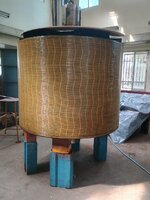
Thanks for so many details.
Most of your answer is aligned with what I was searching for as information.
FYI, they are not PMG used to energize the AVR of a bigger unit. It is really a project using very small hydro generators/turbines. The main generator is 333kW (will probably end up as you said around 400ish kVA when not used at 1 PF). I have very little details right now on the specifics of the possible units to be purchased for that project.

Meanwhile, I'll keep searching for technical articles, books, other references to see if I can find more guidelines on design requirements.
Coco :)
 

Part and Inventory Search

Sponsor