Continue to Site

Eng-Tips is the largest engineering community on the Internet

Intelligent Work Forums for Engineering Professionals

  • Congratulations KootK on being selected by the Eng-Tips community for having the most helpful posts in the forums last week. Way to Go!

Permanent Magnet Synchronous Generator (PSMG) - Searching for references and standards 1

Coco_HueHueHue

Electrical
Apr 8, 2018
49
Hello,

Currently working on a project where we integrate a Permanent Magnet Synchronous Generator (PSMG) into a Distributed Generation plant. I did that in the past for Asynchronous Generator and Synchronous Generator (field excitable), but never for PSMG. The unit is only 333kW. The general installation is a small hydro distributed generation plant.

Can anybody here help me find applicable standards or have a good book reference for that kind of equipment?
All I find is for large hydro unit or wind turbine or car industry. I couldn't find anything for small hydro units of this type.

Searching for information on:
- Functional description (how to drive the voltage output since there is no field excitation and how to put them online and manage their speed - I expect like a DSVC and a governor)
- Recommended Protection and Controls.

Thank you for any help anyone can give me on this.
Best regards,

Coco
 
Replies continue below

Recommended for you

You may have misunderstood the term Permanent Magnet Generator.
Before the advent of PMGs diesel generators supplied power to the Automatic Voltage Regulator from the main generator output.
Some AVRs had sense terminals to sample the output voltage and power terminals where power was supplied to the AVR from the generator output, either directly or by a small transformer.
Some AVRs combined sense and power into one pair of terminals.
This scheme was prone to voltage collapse where a fault or extreme overload would draw the output voltage down and as a result the AVR would not have enough voltage supplied to bring the output voltage back up.
The permanent magnet generator is a small generator that is typically mounted on the generator shaft, outboard of the back end bearing of the generator.
The job of the PMG is to supply power to the AVR.
The last few that I worked on generated about 220 Volts, three phase and were paired with an AVR that expected a 220 Volt, three phase, power supply.
PMG equipped sets avoid voltage collapse and tolerate block loading better than self excited machines.
When ordering a 333 kW generator a PMG may be standard equipment or it may be an extra cost option.
In the event of failure of a PMG or of a PMG AVR, a machine may, in some cases, be operated temporarily with a self excited AVR until spares arrive.
When using a self excited AVR on a system designed for a PMG, fault protection may be compromised and voltage dips due to block loading may be greater.
By the way, did you mean 333 KVA? Generator capacity is limited by KVA, not kW.
kW is a description of the prime mover's minimum capability.
If you need 333 kW, the generator nameplate will probably show:
416 KVA, 0.8 PF.
A 333 KVA machine will supply 333 kW only to a load of unity power factor.
A 333 kW load at unity PF is extremely rare in the real world.
I did that in the past for Asynchronous Generator and Synchronous Generator (field excitable), but never for PSMG
Did you use a CT supplied circuit to provide excitation boost to avoid voltage collapse?
This is not needed with a PMG and PMG AVR.
Your lineup will be:
Speed controlled by a governor that is controlling the prime mover.
Voltage control by set point on the AVR.
Load control by a 5% droop setting on the governor.
PF control by voltage adjustment.
PMG equipped generator and PMG ready AVR.
In a distributed generation scheme, you may generate 333 kW with a 333 KVA rated generator by running at unity power factor.
However you must consult your tariffs to see if running at unity PF will be acceptable.
Some tariffs will specify some amount of KVARs be supplied.
Your no-load, off-line from the grid, speed/frequency will be controlled by the governor.
Your on-line speed/frequency will be controlled by the grid.
Your loading will be controlled by the governor. (Governor set to grid speed/frequency will be zero load. Governor set to grid frequency plus droop percentage, 105% of grid with 5% droop, will be 100% load on the set.)
Off-line your AVR will control the voltage.
On-line the AVR will control the PF and the grid will control the voltage.

Sequence of operation for self excited or PMG excited.
1. Set the governor to the grid speed/frequency.
2. Start the set and bring it up to grid speed frequency.
3. Adjust the voltage to match the grid voltage.
4. Use either a sync check circuit or a synchroscope to connect the generator online.
5. Advance the governor setting to pick up the load. With 5% droop, each 1% additional over-speed will pick up 20% of the load.
Governor setting;---Loading:
100% speed = 0% load.
101% speed = 120% load.
102% speed = 140% load.
103% speed = 160% load.
104% speed = 180% load.
105% speed = 100% load.
Note that the actual speed will be controlled by the grid.
In control engineering terms, we are using the Proportional function of a PID controller. The offset, or difference between the set-point and process variable is what controls the loading.
Adjust the voltage setting too control the PF.
Note: The speed setting and the voltage setting interact.
The normal procedure is to advance the speed setting a little and then adjust the voltage setting a little.
Rinse and repeat until you are st the setting you desire.
 
The beauty of PMGs is that when you turn them, they generate voltage with no external support.
Now getting the voltage and phase correct takes controls.
The permanent magnets are the excitation.
 
You may have misunderstood the term Permanent Magnet Generator.
Before the advent of PMGs diesel generators supplied power to the Automatic Voltage Regulator from the main generator output.
Some AVRs had sense terminals to sample the output voltage and power terminals where power was supplied to the AVR from the generator output, either directly or by a small transformer.
Some AVRs combined sense and power into one pair of terminals.
This scheme was prone to voltage collapse where a fault or extreme overload would draw the output voltage down and as a result the AVR would not have enough voltage supplied to bring the output voltage back up.
The permanent magnet generator is a small generator that is typically mounted on the generator shaft, outboard of the back end bearing of the generator.
The job of the PMG is to supply power to the AVR.
The last few that I worked on generated about 220 Volts, three phase and were paired with an AVR that expected a 220 Volt, three phase, power supply.
PMG equipped sets avoid voltage collapse and tolerate block loading better than self excited machines.
When ordering a 333 kW generator a PMG may be standard equipment or it may be an extra cost option.
In the event of failure of a PMG or of a PMG AVR, a machine may, in some cases, be operated temporarily with a self excited AVR until spares arrive.
When using a self excited AVR on a system designed for a PMG, fault protection may be compromised and voltage dips due to block loading may be greater.
By the way, did you mean 333 KVA? Generator capacity is limited by KVA, not kW.
kW is a description of the prime mover's minimum capability.
If you need 333 kW, the generator nameplate will probably show:
416 KVA, 0.8 PF.
A 333 KVA machine will supply 333 kW only to a load of unity power factor.
A 333 kW load at unity PF is extremely rare in the real world.

Did you use a CT supplied circuit to provide excitation boost to avoid voltage collapse?
This is not needed with a PMG and PMG AVR.
Your lineup will be:
Speed controlled by a governor that is controlling the prime mover.
Voltage control by set point on the AVR.
Load control by a 5% droop setting on the governor.
PF control by voltage adjustment.
PMG equipped generator and PMG ready AVR.
In a distributed generation scheme, you may generate 333 kW with a 333 KVA rated generator by running at unity power factor.
However you must consult your tariffs to see if running at unity PF will be acceptable.
Some tariffs will specify some amount of KVARs be supplied.
Your no-load, off-line from the grid, speed/frequency will be controlled by the governor.
Your on-line speed/frequency will be controlled by the grid.
Your loading will be controlled by the governor. (Governor set to grid speed/frequency will be zero load. Governor set to grid frequency plus droop percentage, 105% of grid with 5% droop, will be 100% load on the set.)
Off-line your AVR will control the voltage.
On-line the AVR will control the PF and the grid will control the voltage.

Sequence of operation for self excited or PMG excited.
1. Set the governor to the grid speed/frequency.
2. Start the set and bring it up to grid speed frequency.
3. Adjust the voltage to match the grid voltage.
4. Use either a sync check circuit or a synchroscope to connect the generator online.
5. Advance the governor setting to pick up the load. With 5% droop, each 1% additional over-speed will pick up 20% of the load.
Governor setting;---Loading:
100% speed = 0% load.
101% speed = 120% load.
102% speed = 140% load.
103% speed = 160% load.
104% speed = 180% load.
105% speed = 100% load.
Note that the actual speed will be controlled by the grid.
In control engineering terms, we are using the Proportional function of a PID controller. The offset, or difference between the set-point and process variable is what controls the loading.
Adjust the voltage setting too control the PF.
Note: The speed setting and the voltage setting interact.
The normal procedure is to advance the speed setting a little and then adjust the voltage setting a little.
Rinse and repeat until you are st the setting you desire.
Thanks for so many details.
Most of your answer is aligned with what I was searching for as information.
FYI, they are not PMG used to energize the AVR of a bigger unit. It is really a project using very small hydro generators/turbines. The main generator is 333kW (will probably end up as you said around 400ish kVA when not used at 1 PF). I have very little details right now on the specifics of the possible units to be purchased for that project.

Meanwhile, I'll keep searching for technical articles, books, other references to see if I can find more guidelines on design requirements.
Coco :)
 
Coco
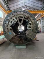
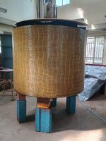
It so happens we are now rewinding a 64 pole, 2.1 MW, 100 RPM, 53.3 HZ Permanent Magnet Motor synchronous motor. The PM rotor pic below.
You can google Oswald Elektromotoren GmbH and ask them about your PM synchronous generators.

Oswald PM Rotor.jpg
 
333 kW is seems really large for a permanent magnet excited generator.
The permanent magnet generators that I have seen have been much smaller.
I see them at around 0.6 kW to 1.0kW.
That is about 0.2% to 0.3% of 333 kW.
They have been used for battery charging, or the output has been rectified and then inverted back to AC.
They have been current limited by a combination of the battery internal resistance and the impedance of the generator windings.
The current may be rectified and then controlled by chopping.
They are typically used with wind turbines and shut down when the battery voltage rises to full charge.
Even smaller PMGs are used on motorcycles for battery charging.
The voltage is limited by a zener diode and excess energy is rejected as heat in the zener.
Many motor cycles depend on a headlight load as well as internal impedance to limit the current.
In many small motorcycles are burned out headlight may be followed soon by a burned out zener diode, in turn followed by the rst of the lamps burning out.
Anecdotally, in many years in the electrical field, I have seen one permanent magnet generator that was voltage controlled internally.
This was a bicycle generator.
One that ran off the side of the tire.
There was a simple, one weight, centrifugal arrangement that forced the rotating magnet along the shaft out of the electrical center of the core and windings.
If you do find a PMG rated at 333kW or similar KVA please share the details with us here.
Caveat:
It is possible to design a permanent magnet generator that will generate a given voltage at a given speed and fixed load.
If the characteristics are similar to a conventional generator, the open circuit voltage may be in the range of 200% before connecting to the grid.
However, you may find a suitable unit in the wind turbine field.
And I did see one other water power generator running without a governor.
Power in was limited by the size of the water turbine.
Speed/frequency was controlled by a voltage controlled load bank.
The project was a failure for a number of reasons and a number of invalid assumptions.
A First Nations elder commented to me;
"If they had asked, we would have told them that that creek goes dry every summer."
Even when the creek was flowing, the unit was too small.
The remote community then purchased a diesel generator and a tank truck to bring in fuel.
Then it was found that the load controlled set was not suitable to run in parallel with the diesel set.
The community was forced to use the diesel set full time and the water powered set sat unused.
Another assumption- Question;
"How was the anticipated load calculated?"
"The government will approve pay for installations up to 50 kW with a simple application. Sets above 50 require a full engineering study, so we applied for a 50 kW set."
"What will you use for a load bank?"
"Hot water tanks. We will also build a laundromat and use the waste heat to heat water for the laundromat. The government paid for that also."
With an undersized set, there was never excess energy to heat the water.
The engineering firm knew more about government ripoffs and effective sales promotions than about engineering.
That was early in my career when I still had a lot to learn about generators and control systems.
If I was faced with that situation today, I would recommend installing a conventional control system and running in parallel with the diesel set.
 
I goggled Oswald Elektromotoren GmbH and found some interesting information.
Their website features a 300 kW, generator that appears to be permanent magnet excited.
It is rated for operation between 1000 RPM and 2200 RPM.
The frequency ranges from 250 Hz at 100 RPM to 550 Hz at 2200 RPM.
Statement:
Variable speed operations without voltage drops
Table:
1000 RPM, 215 Volts
2200 RPM, 519 Volts
?????
These appear to be intended for use with DC converters. (Bridge rectifiers?)
Not suitable for parallel operation with the grid or operation at 50Hz or 60 Hz.
Unless you use conversion to DC and then Pulse Width Modulation to get grid frequency AC.
All it takes is money.
 
"Unless you use conversion to DC and then Pulse Width Modulation to get grid frequency AC."

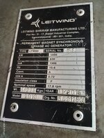
Yes, it's done for wind generators all the time. A 1.5 MW, 15.6 Hz PM Synchronous wind generator in our shop right now, which is connected to 50 Hz grid via inverter. There are many such generators in India alone.

zz.jpg
z.jpg
 
Thank you for sharing, Muthu.
That is the way to go for a variable input speed such as wind power.
I was aware of the technique but had no idea that the generators had grown so large.
But, in the OP's case, with water power, where it is relatively easy to control the speed of the turbine, I think that a conventional AVR controlled generator is the way to go.
Inverters are not cheap.
But, maybe I have made some false assumptions based on incomplete information.
Coco_HueHueHue,
Is there something special about your site that demands a 333 kW permanent magnet generator?
In that case, you may find it more productive to work backwards from the grid through a suitable inverter and then choose a generator suitable to a compromise between the inverter and the available power.
In your position, I would be first looking at available wind turbine schemes, and then engineering to match one of those schemes with the available speed and torque available from the water turbine.
And, that said, I may change my research and design course one or more times as I evaluate various possible solutions.
 
Bill
This beast weighs 42 tons. There are also similar low speed synch machines with higher power rating up to 3.5 MW.
Power to weight ratio is pathetic in such low speed machines. I was told they used a 300 ton mobile crane to bring this machine to the ground level.
 
I think the above deal with most of the questions the OP presented, so the following might be a bit of a rabbit trail.
Wikipedia Link - Permanent magnet synchronous generator (PMSG)

A PMSG can only work as a constant voltage source when the system it connects to has sufficient size to provide the regulation. Output will be directly proportional to shaft input power, frequency (and shaft speed) will be locked to the grid.

If a PMSG is operated stand alone, it's output power and frequency are functions of the shaft speed. The unit will behave as a magneto.

A PMSG will work with a fixed speed wind turbine design, as long as the synchronizing and load rejection scenarios are worked out, and the connected grid is sufficiently stiff.

In the Variable Speed Wind Turbines case one of two types of generators can be used: a DFIG (doubly fed induction generator) or an FRC (fully rated converter). The FRG version will use a PM generator.

Matlab simulation of a PBSG wing turbine operating in variable speed mode.
 
Last edited:
Thank you for sharing, Muthu.
That is the way to go for a variable input speed such as wind power.
I was aware of the technique but had no idea that the generators had grown so large.
But, in the OP's case, with water power, where it is relatively easy to control the speed of the turbine, I think that a conventional AVR controlled generator is the way to go.
Inverters are not cheap.
But, maybe I have made some false assumptions based on incomplete information.
Coco_HueHueHue,
Is there something special about your site that demands a 333 kW permanent magnet generator?
In that case, you may find it more productive to work backwards from the grid through a suitable inverter and then choose a generator suitable to a compromise between the inverter and the available power.
In your position, I would be first looking at available wind turbine schemes, and then engineering to match one of those schemes with the available speed and torque available from the water turbine.
And, that said, I may change my research and design course one or more times as I evaluate various possible solutions.
Hi Waross,

Its only distributed generation one of our client wants to build to sell power to the main utility.
I guess they evaluated to power of the river sufficient to mechanically move this turbine/generator.

FYI, my question was general, so I mentioned 333kW generator.
But, in reality, it will be 4 parallel units for a total of 1300 kW.

FYI #2, I have seen an installation from another client where it was a permanent magnet synchronous generator of..... 10 MVA!!!
I used information from this client a lot to understand better the 300kW unit, I was mainly searching to see if that range of power had the same requirements for control and protection as a 10 MW unit because both are totally not in the same order of magnitude of costs.

Thanks all for your inputs!! Very informative!!
Coco
 
Last edited:
Extracting power from the wind poses some unique challenges that are met by permanent magnet generators.
Typically the output of the permanent magnet generator is a variable voltage and frequency depending on the speed of the wind.
The output iis typically rectified to DC and then inverted back to AC.
The inverter handles the control functions such as load control and voltage control.
The inverter may vary the loading by varying the phase angle of the AC output relative to the grid phase angle.
The ability to control the load allows the inverter to indirectly control the speed and as a result of that, to control the voltage.
In a typical hydro or diesel plant, these functions (speed/frequency) are controlled by the governor and the excitation.
I am not aware of any hydro plants that use permanent magnet generators.
If anyone knows of any permanent magnet generators in commercial hydro service, please share with us.
With a hydro operation, low flow conditions may be addressed by shutting down 3 of 4 units and directing all of the available water to one unit.
This will work with water but not with wind.

, I have seen an installation from another client where it was a permanent magnet synchronous generator of..... 10 MVA!!!
Was this wind or hydro? Please share what information as you are permitted. Thanks.

Does anyone have a cost comparison between a conventional generator and and water flow control equipment versus a permanent magnet generator and inverter?
This beast weighs 42 tons
Hello Muthu;
Can you estimate the cost of that 1500 kW machine as opposed to a similar size conventional generator?
How much will the inverter add to the cost?
And, by the way, did that unit fail as a result of insulation failure or as a result of overload in strong winds?
Thanks.
 
If this will be co-generation and will never be islanded, have you considered induction generators?
You could go with 4 x 450 HP induction motors.
Set the water flow gate manually for about 89% or 90% output and let the grid set the frequency.
Add a capacitor bank to each unit to improve the PF.
This will be the cheapest solution if you can use it.
 
As Bill mentioned - extracting power from wind (or solar) is a highly variable proposition due to the ability of the turbine nacelle to adjust for changes in wind speed and direction (or, for solar, cloud cover and surface contamination). Thus the output of the generator is converted to DC and then inverted to meet the local distribution frequency. Does not really matter what type of generator is actually used - DFIF, PMG, FRC, etc.

Hydro has similar issues - due to variation in water flow to the turbine. To some extent, this can be controlled mechanically (valves/gates).

The complexity of the control is pretty much the same regardless of the output power rating - 100 MVA, 10 MVA, 1 MVA, or even smaller. The capacity of the individual components may well change with the output rating (e.g. highly likely the excitation of a 100 MVA unit will be greater than a 1 MVA unit), but the complexity of how it operates is the same.

As another tidbit: the current generation (no pun intended) of North American DFIG ratings are now approaching 4.5 to 5.0 MW output, with the generator spinning at a much higher speed compared to the blades (typical gear ratio is around 150-to-1). Offshore installations using PM designs (and much closer to "direct drive", with gear ratios in the sub-5 to 1 range) are in the 12-15 MW range. The main limitation for land-based systems is the blade itself - a higher power output generally requires a longer blade which eventually becomes unable to support itself - and the longer blade requires a taller tower. After a point, the mass of the components and the height of the installation (top of the tower) exceeds lift capability.
 
Comparing hydro to wind is not a good comparison.
Wind is a special case.
Typically a prime mover, (hydro, steam, internal combustion engine) may easily bring the generator up to synchronous speed.
Once at synchronous speed and synchronized with the grid, the grid controls the frequency and load and voltage control is straightforward.
Wind power is a unique niche.
Much of the energy extracted by a wind turbine is at speeds below synchronous speed.
This has led to the development of systems where the energy is either generated as Dc or rectified to DC and then inverted to AC at the grid frequency and voltage.
The ability of the prime mover to drive the generator at synchronous speed is a water shed:
If energy is to be extracted from a generator at below synchronous speed, then almost everything changes.
Variable flow has been mentioned in regards to hydro units.
My reaction to that is;
If there is insufficient water flow to bring the set up to synchronous speed, then the set may be grossly oversized for the conditions.
That said, I do not discount that there may be a very occasional exception for a run of the river installation.
 

Part and Inventory Search

Sponsor