Eng-Tips is the largest engineering community on the Internet

Intelligent Work Forums for Engineering Professionals

Perpendicularity of an axis

Status
Not open for further replies.

TomDougherty

Mechanical
Dec 5, 2022
1
0
0
US
Hi, this probably has a super simple answer but I haven't been able to find concrete information on it.

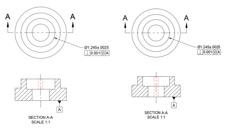
I have a cylindrical part which has a hole that does not go completely through the part (see attached)(I am talking about the larger hole that is dimensioned). I need that hole to be perpendicular to the bottom face of the part (labeled datum A). The tolerance there is just a place holder for now. So for perpendicularity in this case would the tolerance zone be only the depth of the hole (left picture) or the entire length until it reaches datum A (right picture)?

Or maybe a better way to say it is what would be the length of the axis used in the tolerance zone? Only the depth of the hole or the entire axis until the datum? If it is only the depth of the feature then this gives a larger possible deviation in terms of angularity as opposed to the second option.

Thanks in Advance!
 
 https://files.engineering.com/getfile.aspx?folder=4a6e8462-ac0d-4dcf-b5a6-ac604acbf017&file=Axis_Perpendicularity.png
Replies continue below

Recommended for you

To save having to download:
Axis_Perpendicularity_fcwhly.png
 
The first picture. The main backing for this is paragraph 4.1(o) in the ASME Y14.5-2018 standard.

John-Paul Belanger
Certified Sr. GD&T Professional
Geometric Learning Systems
 
If you want the second then you can use the Projected Tolerance symbol and enter a distance, which should give the same control. On the other hand - that's not copy/paste, but it is an extension of principle, so let those two sides fight it out.
 
3DDave said:
If you want the second then you can use the Projected Tolerance symbol and enter a distance, which should give the same control.

Are you sure that if circled P with a distance it is used then the second picture is the correct depicted? I am just asking.
Because I thing the red interuppted line should be shown only for the smalles ID and not on the biggest ID (ID= inside diameter)

Could you, please, clarify?

 
3DDave said:
The projection would be for the feature to which the feature control frame containing the projection symbol is applied.
Yes, but that is not what I was asking.

Where the tolerance zone starts and where it is ending if your proposed P (with the distance) it's used?

 
With the the chain line projection it is explicitly defined as the length of the feature plus the length that is projected.

I was misled because the "small diameter" doesn't matter at all in this case because it doesn't have a related FCF,
 
3DDave said:
With the the chain line projection it is explicitly defined as the length of the feature plus the length that is projected.

If you're saying that the projected tolerance zone extends the length of the tolerance zone by the length of the chain line then no, it doesn't do that. The projected tolerance zone moves the zone from inside the feature to outside. The zone is no longer inside the feature.

John Acosta, GDTP Senior Level
 

I agree with John and that's exactly why I was asking.
It is projected TZ, not extended TZ.

Right picture with red TZ shown does NOT reflect correct definition of the projected TZ.
 
Powerhound - much clearer question; would never have concluded that from greenimi; I agree.

If the projection was from the top surface downward to the bottom surface then it would represent the second case; the standard is silent on that - extension of principle, extension of principle! Nothing says it has to project entirely outside the feature.

But - hey - look at that. Another loose end for the committee to deal with. That's at least 2 more revisions to get right.
 
This brings to mind a further enhancement - that both ends of the tolerance zone might be specified for cases where the mating part is spaced away from the feature exit surface.
 
Regarding

3DDave said:
much clearer question; would never have concluded that from greenimi

3DDave,
With all due respect John's replay was not a question. Was a statement. And he gave you a direct answer/ corrected you.
I intentionally did not want to give you the answer. I wanted to find out if you really know the subject or just try to offer advise without fully knowing the staff or maybe was just a honest mistake.

 
said:
Powerhound - much clearer question; would never have concluded that from greenimi; I agree.

Should I agree more or is this enough?

However, there isn't any thing that prevents the projection from being shown going the other way. Just draw that chain line starting at one surface and projecting back into the part. It's just that the only case the committee envisioned was for press fit pins and threaded studs and that's where their imagination stopped.

Simple.
 
I just did - there is a gap above the mating surface to where the mating part will stop but the holes still need to line up through the thickness of that mating part.
 
Or if the press fit isn't the full depth of the hole, so the origin of the projected amount is only a portion of the depth. No symbolic way to clearly show that.
 
3DDave said:
Or if the press fit isn't the full depth of the hole, so the origin of the projected amount is only a portion of the depth. No symbolic way to clearly show that.

3DDave said:
there is a gap above the mating surface to where the mating part will stop but the holes still need to line up through the thickness of that mating part.

I think ISO GPS (ISO1101:2017) is a little more prepared for what you are asking.
For example, a perpendicularity could be used with the projected tolernace zone (circled P) followed by two numbers/ values
-first value is the length of the projected toleranced feature + the offset of the projected toleranced feature from the reference plane;
-second value being the offset of the projected toleranced feature from the reference plane;

At least that is what I am seeing from figures 72 and 74

3DDave,
Is this what you are asking or I am on a wrong track?

 
Status
Not open for further replies.
Back
Top