Continue to Site

Eng-Tips is the largest engineering community on the Internet

Intelligent Work Forums for Engineering Professionals

  • Congratulations cowski on being selected by the Eng-Tips community for having the most helpful posts in the forums last week. Way to Go!

Pilaster Design in Residential Stemwall 2

Status
Not open for further replies.

medeek

Structural
Mar 16, 2013
1,104
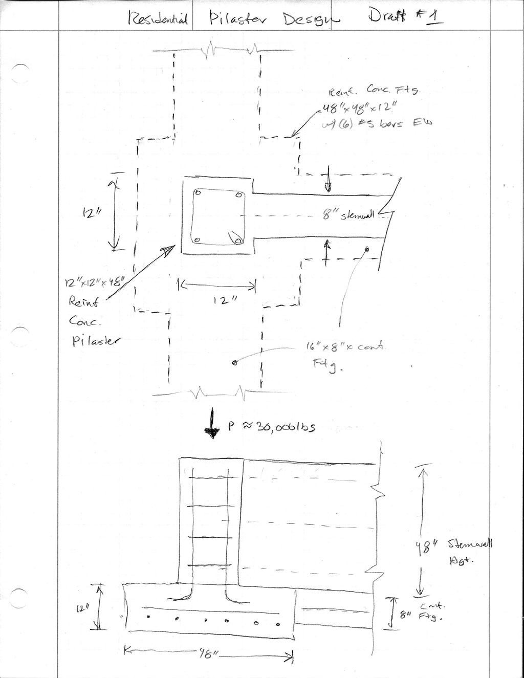
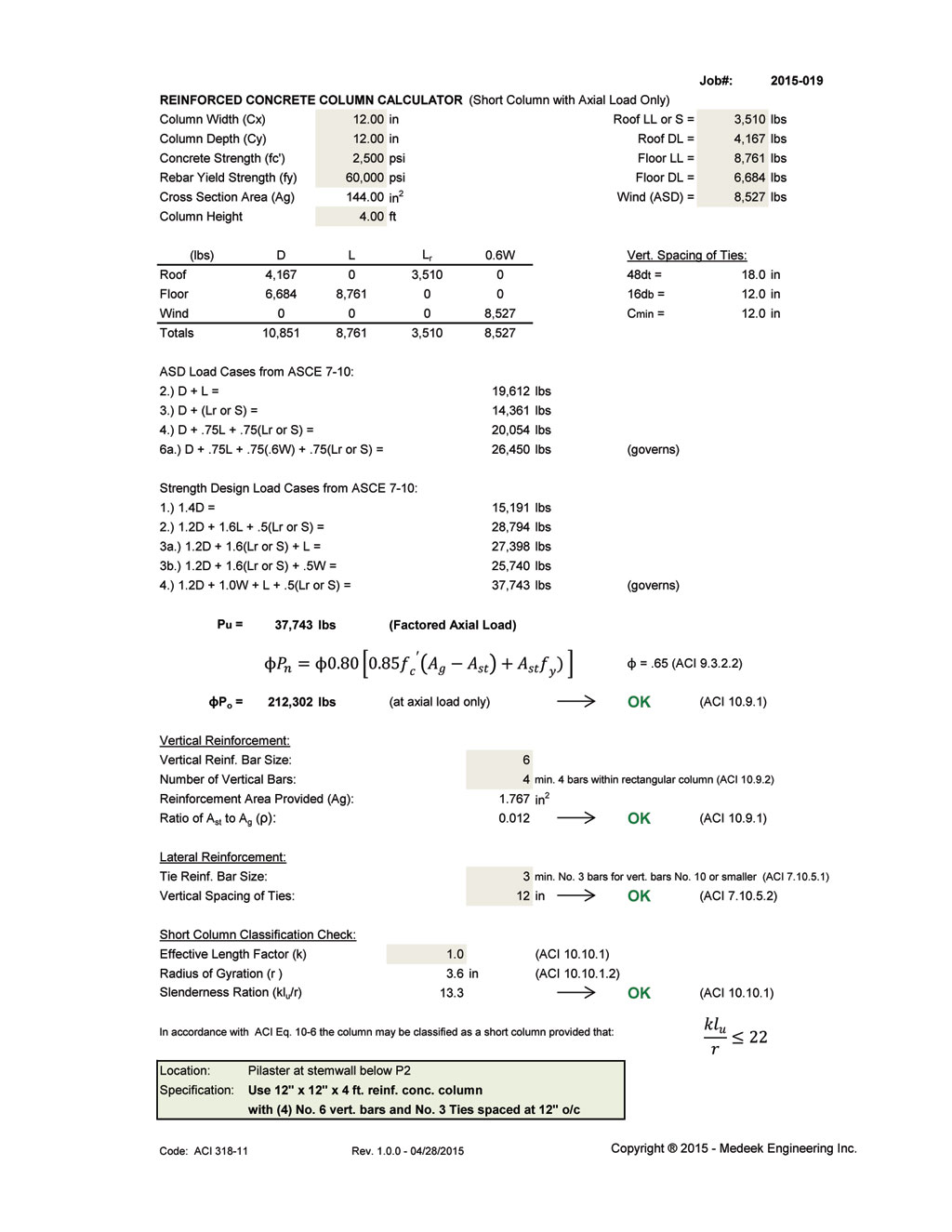
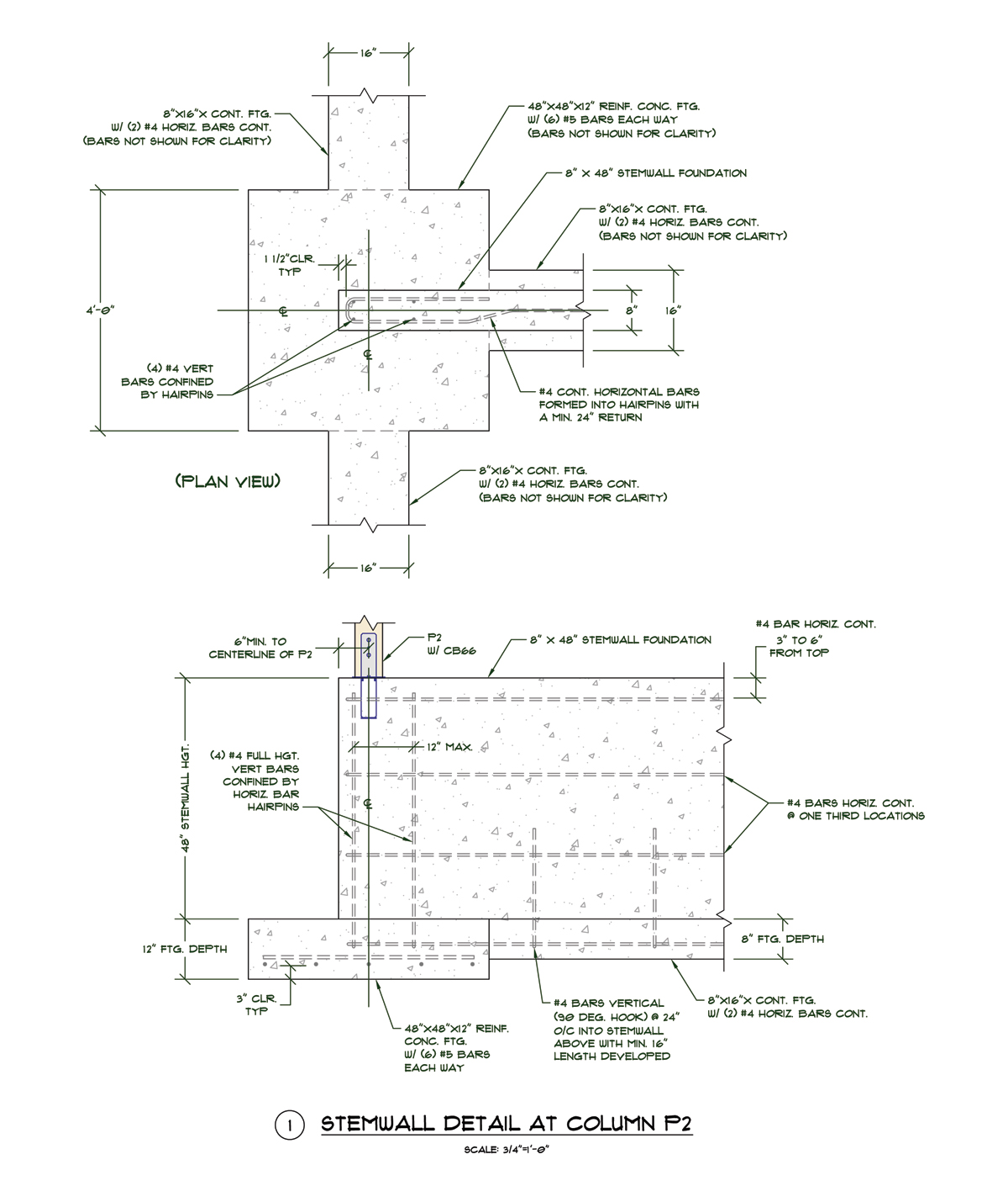
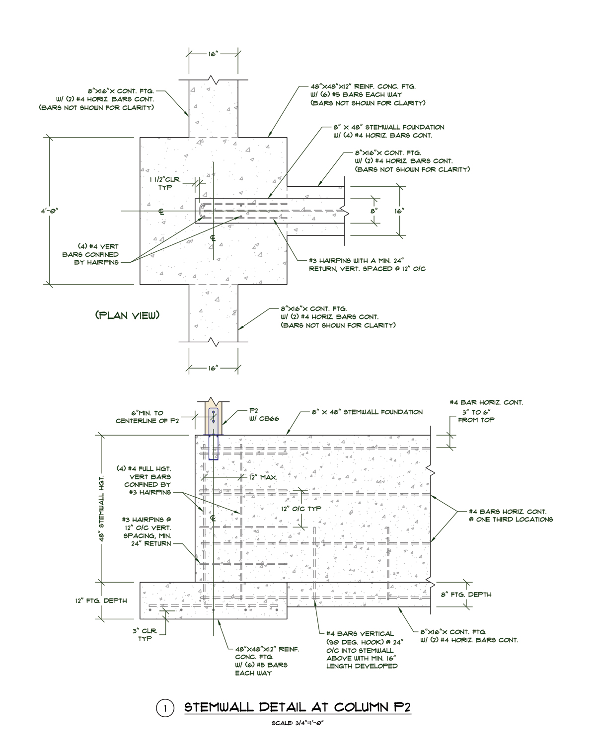
Has anyone ever done a pilaster at the end of a stemwall in a residential design? I have a large point load at the end of a 8" x 48" high stemwall and I am thinking this is the route to go. Are there any prescriptive resources or design guides/spreadsheets?

A confused student is a good student.
Nathaniel P. Wilkerson, PE
 
Replies continue below

Recommended for you

That's a pretty common occurrence. Basically, your pilaster is a short concrete column that's probably braced in both directions by your stem wall. It should be designed as a concrete column but the capacity will likely be vastly more than you require. Here's the procedure:

1) Normally, columns need to have 1% vertical reinforcement minimum. ACI lets your go as low as 0.5%, however, if you reduce your capacity somewhat based on some clause that I can't remember. In short, you'll want 0.5% vertical reinforcing. It's usually efficient to use as few bars as possible. That being the case, I try to keep bars to #6 or smaller in residential applications.

2) Provide ties according to the column provisions in ACI. In the absence of a high shear demand, these are generally based on preventing the vertical bars from buckling. 48 times the tie bar diameter or 16 x the vertical var diameter I believe.

I like to debate structural engineering theory -- a lot. If I challenge you on something, know that I'm doing so because I respect your opinion enough to either change it or adopt it.
 
This is kind of what I have in mind:

PILASTER1.jpg


However, not ever having to design or engineer one of these before has me asking a lot of questions.

First and foremost is how to size the pilaster given the loads and the attached stemwall thickness and also that it is an endwall in the stemwall foundation. 30,000 lbs is not really much when it comes to concrete but when I thought about this much force at the end of an 8" stemwall it did give me some concern.

A confused student is a good student.
Nathaniel P. Wilkerson, PE
 
The detailing appears to be headed in the right direction. As for evaluating the capacity:

1) If you go with the pier, you'll probably want to design it as a concrete column per ACI.

2) If you want to stick with just the wall, there are provisions in ACI for designing walls with concentrated loads that you can use.

When evaluating the wall on its own to resist the point load, it's kind of a tough call to evaluate the bracing situation. If one can count on the soil and slab on grade to brace the wall completely, then you can basically just use the bearing strength of the concrete which would probably work. Certainly if this were a wall corner condition, I'd considering going that route.


I like to debate structural engineering theory -- a lot. If I challenge you on something, know that I'm doing so because I respect your opinion enough to either change it or adopt it.
 
I've created a small spreadsheet to design the pilaster as a short column:

2015-019_CONC_COLUMN_CALCULATOR.jpg


Based on these numbers the 12" x 12" column/pilaster is way over capacity given the loads, I'm wondering if I am too worried about this location and if the 8" stemwall might be fine without any further modification.

A confused student is a good student.
Nathaniel P. Wilkerson, PE
 
I am looking at Eqn. 14-1 in the ACI 318. This eqn. looks like the right one for concentrated loads on walls, now how to actually use it...

A confused student is a good student.
Nathaniel P. Wilkerson, PE
 
Looking at the provisions of Section 14.3 I am wondering how often these minimums with regards to vert. and horz. reinforcement are actually followed in the design and construction of residential foundation walls and stemwalls.

In particular Section 14.3.5 states that vert. and horz. reinforcement should be not spaced more than three times the wall thickness, however I typically call out #4 vert. bars @ 24" o/c for most of my 6" stemwall foundations, technically this spacing should not exceed 18".

A confused student is a good student.
Nathaniel P. Wilkerson, PE
 
Based on equation 14-1 with a wall thickness of 8" and a wall height of 4 ft. and assuming an Ag of 96 in2 (8in x 12in) with a comp. strength of 2500 psi I get a design axial strength of 82,783 lbs. This is more than twice the factored load of 37,743 lbs from my previous worksheet.

What I am a little unclear on is what to take as the appropriate Ag in the equation. Is this a unit area of the wall or is it the actual area of the bearing load (in this case it would be a 5.5" x 5.5" post.

To think that a 8" wall could take a point load of 82,000 lbs (given the appropriate footing/bearing) seems ludicrous but then again I am used to working with wood so my gut instinct on concrete strengths is probably all wrong.


A confused student is a good student.
Nathaniel P. Wilkerson, PE
 
On page 9 of this example problem the Ag is taken as the wall width times an effective length and not the bearing length, I am now thoroughly confused. What is even more surprising is the bearing strength of the concrete under the bearing plate has less capacity than a 15 ft. high wall which seems somehow counter intuitive to me.


A confused student is a good student.
Nathaniel P. Wilkerson, PE
 
a short 8"x12" column as you've designed it would easily hold that. The issue is when you start to account for bending as well that the capacity drops.

I would be checking for bearing capacity under the post but then again, the wood post would govern. and then I could see the load spreading to a 2' wide strip almost, I think only saying 12" is conservative.

are you planning on putting ties around additional bars?

I've put 38 kips on an 8" foundation wall before without even thinking about it. Although my 38 kips may have been more conservatively determined than yours.
 
In reality what I have is a 6x6 LVL post with about 19000 lbs gravity loads coming from the glulam beam above and then a 6x6 chord of the shearwall next to the post with about 9000 lbs tension/compression from wind. So in actuality the the load will be spread over a 6"x12" area roughly, with the bulk of the load on the 6x6 end post.

I think a 8" wall could easily hold the load but if it was in the middle of the wall but I'm applying this point load at the endwall situation, my worry is the concrete spalling or shearing off in some weird failure mode that might be hard to account for.

A confused student is a good student.
Nathaniel P. Wilkerson, PE
 
In my residential market (1/2" or 5/8") 40k rebar rod is all that is used
 
If you hooked your horizontal bars and maybe provided one or two extra near the top you'd likely be ok.
 
Explain the hook, I'm assuming its a 180 degree and it extends back on itself for a foot or two to achieve further development.


A confused student is a good student.
Nathaniel P. Wilkerson, PE
 
I was just thinking a 90 with a 6" long leg that you turn each bend towards the other wall face, essentially turning your horizontals into a stirrup of sorts at the end. I know you aren't getting enough embedment length but it's better that nothing. On second thought, I think I like providing hairpins at the end of the wall to confine the end two verticals.

I'm just suggesting things to try and mitigate your blowout concerns. I actually think your spalling/splitting concerns are reasonable, I can picture a wedge of concrete at the top of the wall trying to come off.
 
Jayrod12 I think you've hit on the appropriate solution for this situation. I will provide a small detail with two vertical bars at the end wall and the horiz. rebar wrapping around them and then back at least 24". This should be a good compromise between a full column/pilaster design and no treatment at all. I just found a similar detail online that deals with an endwall in almost the same manner.

I think capacity was never as much of an issue here as was my concern of a "blowout" at the end/top of the stemwall. I appreciate everyone's suggestions and help. I now have two new spreadsheets for concrete columns and walls as well as a much better idea how to deal with concrete walls in the future.

A confused student is a good student.
Nathaniel P. Wilkerson, PE
 
I bet the contractor would rather just provide hairpin dowels with a 24" leg on each side as opposed to being the horizontal bars. Just for constructability.

And that would likely be ok in my eyes.
 
Status
Not open for further replies.

Part and Inventory Search

Sponsor