Continue to Site

Eng-Tips is the largest engineering community on the Internet

Intelligent Work Forums for Engineering Professionals

  • Congratulations SSS148 on being selected by the Eng-Tips community for having the most helpful posts in the forums last week. Way to Go!

Pin Plate Supports

Status
Not open for further replies.

ILL_INI

Structural
Mar 23, 2020
9
Hey group,

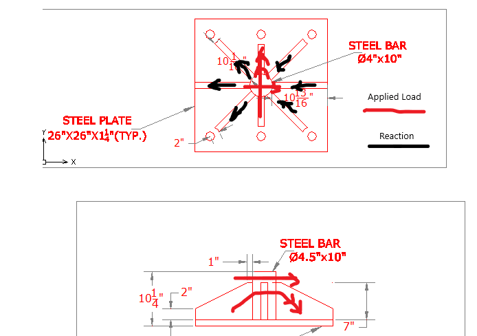
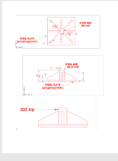
I am a very green structural engineer(great timing). I am designing a base plate with a pin to connect to another pin plate that could have axial loads as high as 300 kips. I am not sure what method is best to size and detail the plates around the pin. I was considering idealizing the 300 kip force as an equivalent force at the point of the pin that connects to the top of the gusset plates. I would then idealize the plates as struts and then make sure all the forces cancel out like a truss node. I think this is pretty conservative and I'm not sure if it is the standard way of doing things. I don't have access to much design software. If anyone has any tips or resources that may be helpful, I would greatly appreciate it.

Thanks!
 
 https://files.engineering.com/getfile.aspx?folder=cce13532-653c-47ce-aa1c-cc93fede8758&file=NewBase.pdf
Replies continue below

Recommended for you

The most basic answer would be to follow the load path. You can make the connection behave as needed by sizing your welds and plates to take the load where you need it to go. Your 300 kips is going to be distributed from the central rod to the base & radial plates. Start by sizing the welds that transfer the force at those joints. Be sure to provide at least a 0.75" clip so an all around weld can be applied to the central rod. That will establish the initial load dispersion. Next, select a minimum size for the radial plate, so the base metal will not govern. Check the other limit states of the individual plates, for the proportion of the total load you are attributing to them. The next transfer is thru the radial plate to the base plate. You can use the generalized elastic method if you want to consider the eccentricity of the load on the weld group at the bottom of the radial plate. It will be conservative due to the inherent nature of the elastic method. If you need a weld group solver, do a google search for "Alex Tomanovich weld group excel". The load will then go thru the base plate and into the base plate anchor rods. There are a number of different ways you can resolve the different prying action cases you'll have.

If you can get that far, some greybeard shouldn't have a problem helping you make your design conform to your company's preferences.

This answer might be a little more generic then you wanted, but you can do certainly create a winning design without resorting to numerical methods.
 
Follow the load path, as the good Dr. says above.

You say axial, which I would take to mean axial to the central rod, but you show it as a horizontal load. In which direction is the load? All possible directions?

If it horizontal, you might look at the anchor bolts first. The number and size of anchors may dictate the geometry of the rest of the assembly.
 
JLNJ,

Sorry for the confusion. The load is as shown in the drawing. I meant to say that the connecting member to the central rod could have axial loads of 300 kips (C or T).

I have already designed the anchor bolts and the base plate for the eccentricity of the load to the faying surface (Case 1) per Chapter 7 of AISC 15th Edition.

Thank you for your response.
 
Dr. ZoidberWoop,

Thank you for the detailed response. I was hoping there was a standard method somewhere in AISC, but I will begin doing what you suggested.

Thanks for the weld group solver. Honestly, we didn't spend that much time on connections in class so I am still learning on that front.
 
Good luck. I completely understand. I was in the same boat years ago. I'm a steel connection design PE for a fabricator, and I still get my mind boggled everyday. Working through problems like this is how you earn those grey hairs.

This is a link to a thread where I posted a .pdf with a breakdown of some very basic welded connection cases. It includes a step-by-step guide describing the generalized elastic method used in the weld group solver I referenced earlier.
 
Blodgett takes on base plates with brackets in his book: 'Design of Welded Structures'. He doesn't quite have this situation.....but the concepts used are similar.
 
This is a look simple but highly difficult/complicate design. You first have to determine the share of the stiffener plates in resisting the horizontal load, find the resulting stresses - shear and flexural, and make sure the plates are up to task (will not buckle), then design the welds. I'll shy away from hand calculation, to me, a 3D computer model is necessary, and is a more realistic approach.

p_kfev94.png
 
Clarification required. Which direction is the applied load?

BA
 
The load is applied as Retired13 illustrated, although the angle off the X axis could vary slightly (reason for this design as opposed to using a pin plate welded to a W section)
 
BA,

This is the original provided.

n_vsi1yy.png
 
Yes retired13, I saw the original, but the OP stated the load was axial. I interpreted that to mean axial with respect to the cylindrical steel bar, not normal to the bar.

Now I am wondering how the load is applied as illustrated and how such a condition occurs in an actual structure.

BA
 
BAretired,

I should have clarified that the incoming force was axial along the member connecting to the pin plate in question. I said axial to imply that it would always be in the plane shown (perpendicular to the center bar). This built up pin plate is a temporary connection from the building slab to a large, freestanding structure. It is not the typical industry designed connection, but I am trying to come up with a modular connection that eliminates the large eccentricity and p-delta effects from the massive axial load if we were to use one-piece construction for the whole member. (Like a W12x120 just welded to the base plate and spanning 25 ft to the next structure.)

I hope those extra details help clear things up.

Thanks for the discussion.
 
ILL_INI:
What size is the round pin, 4 or 4.5” round? Since it is 10” long, I assume you are putting it down into a like dia. hole in the base pl., so that you can put a fillet weld on the underside to the base pl. and then another larger fillet on the top of the base pl. also, that’s good. Your last post didn’t clear things up much, but I assume the load is generally along the x-axis, +/- 5° either side, and it can be pushing or pulling along that axis. The W section bit, I don’t understand. Then, put 4 A.B’s along the left and right edges of the base pl., and eliminate the stiffeners on the z-axis, and those two A.B’s. since they don’t do much for this load. You might move the diag. stiffeners to 60° from the x-axis, this will give you a little better welding access btwn. the tiff. pls. and the pin. The two stiff. pls. on the x-axis will take 60-70% of the load down to the A.B’s. What holds the pin pl. on the pin, and what dia. is its hole w.r.t. the pin dia., and is the pin pl. just resting atop the stiff. pls. What takes the 300k shear at the faying surface at the bot. of the base pl.? Do you need some sort of a shear lug there?

Edit: Is this a support for a tower crane, or an elevator, or some such? Give us a hint, instead of the 20 questions game.
 
BA,

And I don't understand the "pin" situation the OP addressed in the opening, unless he meant the late was assume pinned to the floor. But what is this meant "a base plate with a pin to connect to another pin plate", the plate assembly rather is rigid, otherwise, IMO, it won't survive the load.

The most simple way to design, I think, is to assume only the elements in line with the applied load are effective in resisting the load. Even with that simplification, I'll need time to think about.
 
dhengr,

Sorry, I wasn't trying to be frustrating on purpose. I didn't know what level of detail was needed.

It is for a tower crane. I am trying to have a moment release condition at the slab so that I can use smaller W-setions for the tie while also having the ability to adjust the angle for the install to the crane collar. The company I am designing it for wants to precast the anchor holes. I explored slip-critical connections and over-sized holes to gain my angle adjustment, but they don't have the capacity given my plate and bolt pattern. The bolt pattern is determined by the company I am designing for. Instead, I am designing as a bearing type connection to the slab with A193 threaded rods.

The pin is most likely going to be 4.5" because I do not believe the 3" pins have the moment capacity even though protrude 3" above the stiffeners and I am worried about the plate bearing strength.

My initial thought is that the connecting pin plate can rest on the stiffeners. Is this a bad idea?

I am not sure about the mechanism to keep the connecting pin plate onto the pin rod. We usually use cotter pins, but they are always oriented on the bottom of the pin.

I like your suggestion of the hole in the base plate and the fillet welds on the top and bottom. I had not considered that.

The pin plate diameter can be whatever I design it to be. It is usually 1/8" larger than the pin rod.
 
Capture_oxytte.jpg


The original post was about designing the supports around the center rod (pin). I had researched gusset plate design, but I was wondering if there were any people that deal with this type of stiffener design more often that could share some insight.
 
I too need more time to reflect on it, but:
1) should the WF be rotated 90 degrees so that the pin plate bears against the web of the beam?
2) the direction of axes is not consistent. I assume that the Z axis should be parallel to the axis of the cylindrical bar on the first edit: second sketch.

BA
 
If I understand correctly, the plate assembly is pre-assembled, the OP is required to design the anchors to hold it to the floor, and link an arm from the tower crane to this assembly. Then, plate won't work, a sturdy solid rod with eye bolt may be is in the order.

BA, good catch on the Z-axis.
 
The axes were just part of the dwg that I threw together real quick. They have no real relevance to the picture and I should have cropped them out. I just wanted to include a plan and elevation view of the rod base plate.

Also, the W14x99 is just an example of the type of tie connected to the pin plate assemble.

Lastly, the bolting pattern and the relative footprint of the base plate are predetermined by the company this is being designed for. Everything else is up to me. I am just trying to find a method to size and show the strength of the stiffening plates around the center rod.

I appreciate the discussion and all the help.
 
Status
Not open for further replies.

Part and Inventory Search

Sponsor