Continue to Site

Eng-Tips is the largest engineering community on the Internet

Intelligent Work Forums for Engineering Professionals

  • Congratulations waross on being selected by the Eng-Tips community for having the most helpful posts in the forums last week. Way to Go!

Pinned Concrete Slab to Concrete Beam/Wall Connection

MountainManMatt

Structural
Jul 20, 2015
2
I have a question about elevated concrete slab design/detailing. Does the condition shown below meet the requirements of ACI? Can shear friction account for the shear transfer across the cracked joint? The goal is to assume a hinge for analysis purposes. Does the direct interaction of concrete below the reinforcing develop a negative moment? If so would the shear depth of the slab for shear capacity then be 1"?
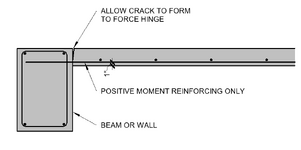
1731543161650.png
 
Replies continue below

Recommended for you

I'm also learning through books. So excuse me if my comment is irrelevant.

Don't know about ACI. However I feel like you should not consider the concrete (the cover) below r/f for any analysis purposes. It would develop some degree of negative moment, but I feel it's negligible considering you check the slab if it needs shear r/f and top r/f (if it needs doubly r/f etc) in addition to the bottom r/f you have already placed (usually any engineering code would have checks for that than blindly using singly r/f).

For analysis purposes, I would just ignore the small negative moment, so it would add to the maximum bm at the mid section of the slab.
However, since it's beam-slab connection, you can do the fixed end moments and in that way you can calculate the hogging moments at the connection as well. You need to account for the hogging moment as well, as you have to place top r/f at least 1/8 distance from the connection + bond length.

I could be wrong though.
 
I'm not that familiar with ACI, but I would not detail it like that.
I feel like RC design is often thought of as "elastic" design, but it really requires you to think in plastic terms, or at least consider the cracking.
I would add a hairpin to connect the beam and slab (that is how it's done in my area)... in other words I'd deffinitely have top reinforcement. The question is "what is a hinge"? It is theoretically a connection that transfers 0 moment and has infinite rotation capacity. In reality anything that transfers a small moment and rotates a lot is good enough to be considered a hinge. In Eurocode this is solved like this "consider the connection pinned, but add at least 25 % of bottom reinforcement to the top of the slab".
The point is this - you are designing for ULS, so you're supposed to model the structure in that condition. If you add minimum reinforcement to the top what will happen? When the load is very small it will act as a fully fixed joint. Increase the load and at one point top reinforcement will start to yield. What happens when you increase the load further? That section still transmits the same (small) negative moment and starts rotating, but positive moment at the middle of the slab span increases. So, from yielding of the top reinforcement until failure of the slab it will deffinitely be a hinge. Theoretically you could "reduce" the midspan moment because of that small moment at the edge, but why bother?
Another thing here (maybe even more influential in this specific case) is that making this a fixed connection would require the beam to transmit torsional moment and torsional rigidity of a beam is small, especially when it cracks (and it most deffinitely will).
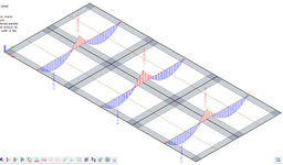
For comparison look at the two following pictures - they show bending moments in a plate (20 cm thick) at ULS. They are all supported on beams with w/h = 30/60 cm. At beam intersections are supports (colums for example). You can see in the first picture that the torsional stiffness of the beam is quite low, so you get a relatively small bending moment at the edge.
01.PNG

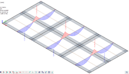
If you assume that outer beams will be cracked torsional stiffness drops to about 10 % of the original value, so you'd get something like this:

02.PNG

This is pretty much a hinge at the edge. See how the rest of the moments barely change. From a design point of view it makes sense to simplify it and say that torsional stiffness of the outer beams is 0 and put some small top reinforcement in the slab anyway. That way you control the top crack and can transfer a small moment, but allow the rotation.
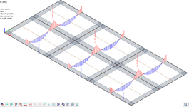
Now let's look at the case where the beam is 150 cm high and 40 cm wide. This would be quite unusual, but just to get the feel. You can see the bending moments in the picture below.
03.PNG

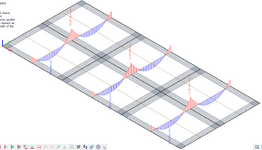
Of course, edge moments are really high (basically a fully fixed connection). If you consider the beam to be cracked and lower the torsional stiffness to 10 % you get a significant drop in the edge moments as per picture below.
04.PNG

Now, again... I could design this by saying that this outer connection is hinge, but here I would expect much larger cracking if I were to design it that way so I'd probably add more than minimum reinforcement at the top. That is the thing, if you have a reasonable ductility capacity, you can choose where the hinges form and how much moment they transfer - as long as it's statically determinate (and not a mechanism) and as long as you transfer all the loads (if the sum of bending moments is w*L^2/8 and sum of shears is w*L). Larger deviation from the elastic solution means more cracking so that may be a problem.

Hope this helps.
 
Does the condition shown below meet the requirements of ACI?
NO ! .. You are expected to provide at leat min . top reinf.

The goal is to assume a hinge for analysis purposes..
If the slab supported on end beam ( the slab is not continuous ) . You can model simply supported although the beam will resist with torsion but will be negligible . If the side support is a wall , in this case the slab can be assumed continuous if there is no cold joint btw slab and wall .

If exterior support is a beam , it is common practice to assume simply supported slab and provide top reinf. at least 50% of span reinf.
 
NO ! .. You are expected to provide at leat min . top reinf.


If the slab supported on end beam ( the slab is not continuous ) . You can model simply supported although the beam will resist with torsion but will be negligible . If the side support is a wall , in this case the slab can be assumed continuous if there is no cold joint btw slab and wall .

If exterior support is a beam , it is common practice to assume simply supported slab and provide top reinf. at least 50% of span reinf.
I’m trying to make this point in an internal debate. I agree that this detail is not a good detail, but I am having a hard time putting the code references together. ACI seems pretty explicit about top reinforcement for two-way slabs but the one-way slabs section doesn’t refer to those detailing requirements (that I have found).
 

Part and Inventory Search

Sponsor