Continue to Site

Eng-Tips is the largest engineering community on the Internet

Intelligent Work Forums for Engineering Professionals

  • Congratulations IDS on being selected by the Eng-Tips community for having the most helpful posts in the forums last week. Way to Go!

Pipe dimension between to level tanks 3

Status
Not open for further replies.

DRQ

Agricultural
Feb 18, 2020
9
Hi all,

I have a small problem i would like your help with. I am more interested in how to do the calculation so i can do it in the future than the solution itself :)
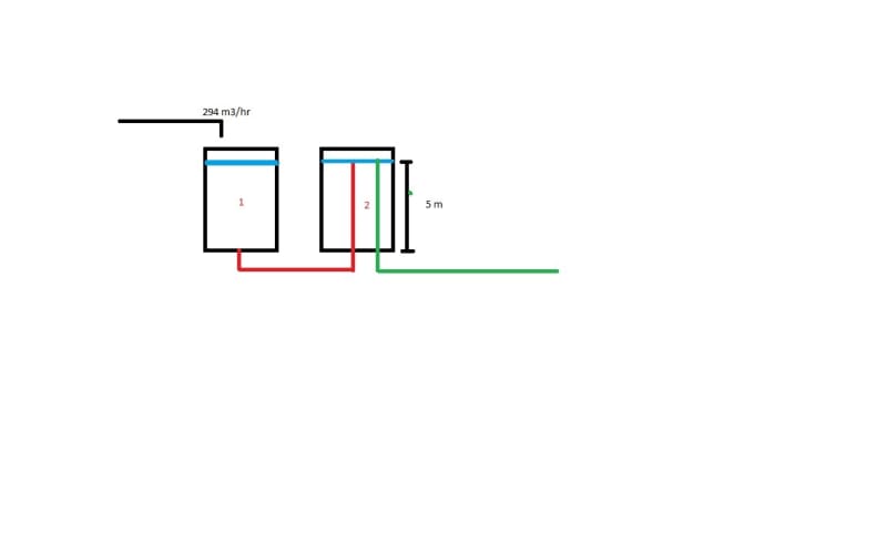
I have two tanks, different volumes but both six meters high and I want to dimension the pipe between the two tanks.

see the attached drawing for a quick illustration but the point here is that in tank 1 the outlet is at the bottom and the inlet into tank 2 is at 5 meters and this is setting the water height in tank 1.

Flow into tank 1: 294 m3/hr
Flow out of tank 1: 294 m3/hr
Density of fluid is 999kg/m3
Outflow coefficient in tank 1 is 0.82

liquid height in tank 1 should not exceed 0.5m above outlet in tank 2, or 5.5 meters.

is suggesting 11.51 inches/0.292 meters in diameter, but again no calculation steps.


Tanks_vyodjz.jpg


Thanks
 
Replies continue below

Recommended for you

So the maximum differential head between top of liquid in tank 1 and exit from the pipe in tank 2 is 0.5m

There are many programs and tables which will let you size the pipe based on flow and length of pipe as your pipe will be 100% full. The site you quote is for an overflow pipe which runs only partyl full.

what will be more difficult though is working out what happens in tank 2. not really sure what you mean by outflow coefficient. How do you convert this to a meaningful number in terms of pressure or head?

If your velocity is too high it could hit the roof or create a lot of turbulence.

If there is some sort of elbow, expander, tee piece, cap or something else which restricts velocity or lets the flow disperse then this will add flow resistance which could be significant for such a short(??) line

Out of interest, what height is the green line and what diameter is that? That green line would be only partly full and would need to be bigger than the intertank line

Remember - More details = better answers
Also: If you get a response it's polite to respond to it.
 
To get to a real-world answer you need to confirm an assumption, and give some additional details.

The assumption is that capacity of the green line is much more than 294 m3/h so that it is safe to assume that the level in Tank 2 is fixed at 5 m. This is needed to fix the pressure drop across the red line.

The additional information needed is everything required to determine the pressure drop through the red line as a function of its diameter. What is the total length of the red line? What fittings are in it? What is its roughness?

Katmar Software - AioFlo Pipe Hydraulics

"An undefined problem has an infinite number of solutions"
 
Hi @LittleInch,

So the maximum differential head between top of liquid in tank 1 and exit from the pipe in tank 2 is 0.5m - Yes that is correct, the maximum water rise in tank 1 must be 0.5 m.

what will be more difficult though is working out what happens in tank 2. not really sure what you mean by outflow coefficient. How do you convert this to a meaningful number in terms of pressure or head? - Well i tried to approximate it as flowrate calculation for draining a tank with constant water level (0,5 m, maximum water height above the pipe) and with a bottom outlet to calculate what area size for the outlet was required, hence the outflow coefficient/discharge coefficient.

If your velocity is too high it could hit the roof or create a lot of turbulence. - Sorry i should have mentioned that both tanks are open and 6 meters high, so i am not worried about that.

Out of interest, what height is the green line and what diameter is that? That green line would be only partly full and would need to be bigger than the intertank line - Height of the green pipe is is 5 meters and it is 730 mm in diameter, so capacity there should not be an issue.

hi @katmar

The assumption is that capacity of the green line is much more than 294 m3/h so that it is safe to assume that the level in Tank 2 is fixed at 5 m. This is needed to fix the pressure drop across the red line. Yes, the green pipe is 730 mm in diameter so it would not constrict the flow in any way.

The additional information needed is everything required to determine the pressure drop through the red line as a function of its diameter. What is the total length of the red line? What fittings are in it? What is its roughness? - There is two 90­° bends, a valve (k-factor unknow as it is still in development at my supplier) 20 m of PE pipe in total with a roughness of 0,03 mm (high for PE, but assumed for safety).

@katmar, just to check if i understand your thought process correctly, the pressure drop in the pipe should equal the water level difference or head in the two tanks and i should be clear or? Because using a 318 mm pipe (i know it is not a standard pipe size) two 90° bends and a gate valve, i am getting 0,24 m head loss.


Whatever pipe size you turn up with I would recommend the end is a reducer whereby you at least double the square area or even treble it so the water just sort of seeps out the edge and doesn't generate any sort of a jet or water column.

With only a maximum of 0.5m water head to drive your flow you don't really want anything creating a pressure /head at the far end.

Based on that calculation I would go for a 315mmPE pipe myself.

Remember - More details = better answers
Also: If you get a response it's polite to respond to it.
 
@LittleInch

Thanks for your answers and time.
Just to understand you correctly, you are advicing to ioncrease the pipe size towards the outlet just to reduce the flow velocity, correct?

Thanks again!
 
The height of the "jet" exiting the pipe cannot be higher than the water elevation in tank 1. Just out of curiosity, what is the purpose of this tank arrangement?
 
Correct.

Remember - More details = better answers
Also: If you get a response it's polite to respond to it.
 
Hi @Compositepro,

The purpose is aquaculture, the tank with the green pipe will maintain the level in several other tanks and only have one retun pipe to the filtration system, the pipes in tank 2 can be lowered/raised.
For the purpose of keeping things simple i did not mention it.

I have no problems with the pipe flow calculations but i just can't figure out what if its just pressure loss vs head or something else is at play.

 
@DRQ - Yes, all that is at play is the available head vs friction loss calculation. The outlet of Tank 1 should be treated as a square edged pipe inlet with a K-value of 0,5 rather than as an orifice as you have done. My calculation based on this type of pipe inlet, 2 elbows, a gate valve, one exit loss and 20 m of straight pipe agrees with yours for the 318 mm ID pipe. The exit velocity will be only 1,03 m/s and the jet will rise about 50 mm. If this jet height sounds excessive you could install the outlet reducers that LittleInch suggested.

I agree that the 730 mm outlet pipe will not constrict the flow.

Katmar Software - AioFlo Pipe Hydraulics

"An undefined problem has an infinite number of solutions"
 
Thank you all for your answers!
 
Status
Not open for further replies.

Part and Inventory Search

Sponsor